In high-precision welded tube manufacturing and roll-forming operations,
entry-end material handling dictates the continuous momentum of the entire mill
line. Raw steel coils, ranging from cold-rolled carbon steel to high-strength
stainless alloys, require steady, controlled unwinding before entering forming
pass rolls, high-frequency induction welders, and sizing stands. While fully
automated hydraulic systems dominate ultra-high-speed production, utilizing a
manual decoiler provides an economical, robust, and dependable solution for
light-to-medium gauge pipe mills, profile forming lines, and targeted production
runs.
Strip tension anomalies at the entry stage cause misfeeds, edge damage, and
premature roll tooling wear. Achieving smooth strip payout without complex
hydraulic circuits or electrical drive units depends on mechanical integrity.
Evaluating structural frame rigidity, expansion mechanics, friction braking
torque, and strip alignment protocols allows mill supervisors and plant
engineers to maintain seamless material feeds while minimizing capital
expenditures and routine maintenance overhead.
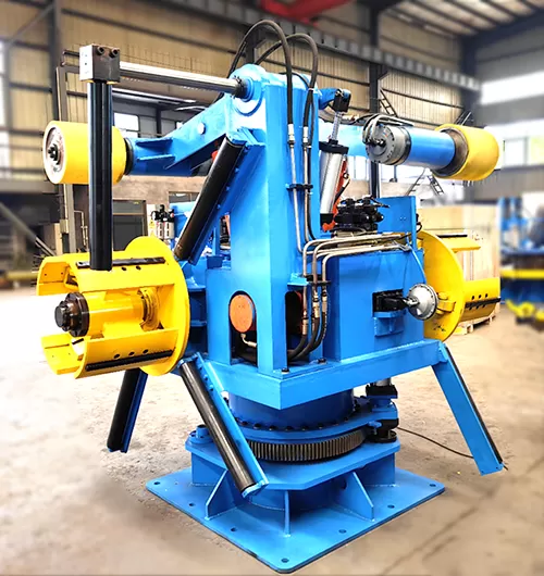
Structural Architecture and Mechanical Functionality
The core purpose of coil payload equipment is to secure raw steel rolls
internally and permit smooth rotational payout under controlled resistance. The
operation of a manual decoiler relies on simple mechanical physics rather than
fluid power or electrical synchronization. Structural stability begins with a
heavily welded steel base, designed to anchor securely to the shop floor and
absorb rotational torque, off-center loading, and axial vibration during
high-speed line operations.
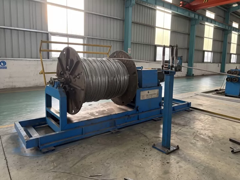
At the center of the unit is the main spindle, a high-tensile forged steel
shaft mounted on heavy-duty tapered roller bearings. These bearings handle
substantial radial forces from the coil weight alongside axial thrust generated
during alignment adjustments. Suspended from the spindle is an expanding
mandrel, typically composed of three or four segmented steel arc segments.
Mandrel Expansion Mechanics
Coil clamping relies on mechanical wedge expansion. Operators manually turn
an external drive screw or mechanical hand crank positioned on the front face of
the spindle hub. Rotating this central shaft pulls or pushes internal wedge
blocks along inclined slider tracks. As these wedges slide along the axis, they
push the mandrel segments outward in unison.
Symmetrical Radial Expansion: Equal outward movement across
all segments ensures the coil inner diameter is gripped evenly without causing
localized deformation to the inner wraps.
Manual Locking Torque: Screw-thread leverage provides
strong mechanical clamping power, keeping heavy metal coils tightly centered on
the spindle during full rotational speeds.
Broad Grip Range: Adjustable jaw expansion accommodates
varying inner mill coil diameters without requiring adapter rings or custom
sleeves.
Mechanical Braking and Tension Control
Because non-powered decoiling equipment relies on the downstream forming mill
or pull-through flattener to pull the strip, controlling rotational inertia is
important. Without dynamic resistance, coil momentum causes over-rotation during
mill deceleration, producing loose wraps, material tangles, or dangerous strip
slippage.
A manual decoiler uses an adjustable friction brake system attached to the
main spindle shaft. This setup generally consists of a cast-iron brake disc or
drum clamped by high-friction composite pads or a heavy-duty friction band.
Operators adjust strip tension manually via a spring-loaded mechanical
handwheel. Tightening the spring increases clamping force on the brake disc,
applying precise resistance against strip drag. This simple mechanism prevents
coil overrun and maintains uniform strip flatness across entry guide tables.
Strategic Integration within Welded Pipe Production Lines
Integrating uncoiling hardware into a continuous welded tube mill requires
exact alignment along the mill centerline. Misalignment between the pay-off
stand and the initial forming pass causes strip edge buckling, camber errors,
and unequal stress distribution during high-frequency welding.
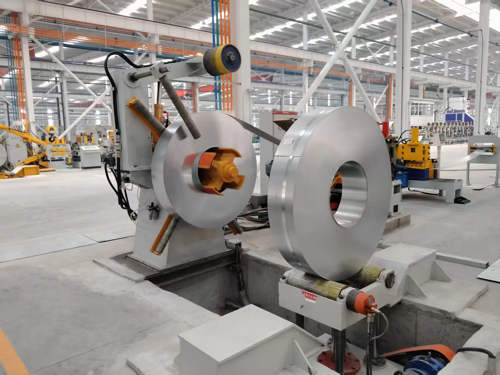
Positioned at the head of the mill line, a manual decoiler serves as the
primary uncoiling hub, feeding material directly into end-shear welders, strip
accumulators, or leveling units. Machinery manufacturers like SANSO design
cantilevered spindles mounted on sliding bed bases. These adjustable bases move
sideways along precision keyways via a manual lead screw, allowing operators to
make micro-adjustments to the strip path without unmounting the heavy coil
payload.
Material Handling Across Strip Profiles
Varying strip dimensions and material grades exert unique physical forces on
entry machinery. Understanding material dynamics ensures stable feeding across
processing lines:
Low-Carbon Steel Strip: Offers predictable ductility;
requires steady brake tension to maintain center pass alignment through initial
breakdown rolls.
Stainless Steel Alloys: Features high surface finish
standards and elevated yield strength; demands non-marring mandrel segment
covers and precise back-tension to prevent surface scratching.
Galvanized and Coated Steels: Requires smooth jaw clamping
to avoid flaking protective coatings off the inner coil loops during
expansion.
Evaluating Load Mechanics, Friction Control, and Ergonomics
Selecting appropriate coil handling equipment requires evaluating structural
load boundaries against operational ergonomics. Cantilevered shafts experience
extreme bending moments at the rear bearing housing. Calculating shear stress
and deflection limits ensures long-term operational reliability without shaft
failure or spindle sagging.
When loading a steel coil onto an unpowered mandrel, operators slide the coil
axially onto the collapsed segments using an overhead crane, C-hook, or forklift
boom. System geometry must support these cantilevered loads without structural
deflection, which could distort strip tracking into downstream leveling
rolls.
From an operational safety perspective, manual mechanical expansion reduces
reliance on high-pressure hydraulic lines, eliminating fluid leak risks, thermal
oil degradation, and electrical pump power demands. Heavy-duty mechanical thrust
bearings inside the expansion screw assembly reduce physical effort for line
operators, allowing rapid coil loading during changeovers.
Selecting the optimal coil entry system depends on duty cycles, strip
thickness, coil weight, and planned line speed. While hydraulic automated payout
reels suit ultra-heavy, high-speed applications, unpowered systems offer
distinct mechanical and operational advantages for specific tube mill
configurations.
Capital and Maintenance Overhead: Unpowered mechanical
units require significantly lower initial investment. Without hydraulic power
units, proportional valves, or complex electrical panels, routine maintenance
centers mainly on bearing greasing and friction pad replacements.
Operational Simplicity: Simple mechanical adjustments
eliminate software troubleshooting, sensor recalibration, or hydraulic seal
rebuilding, maximizing productive mill uptime.
Footprint Efficiency: Lacking external hydraulic tanks and
control cabinets, unpowered units fit compactly into limited shop floor spaces,
making them ideal for specialized profile lines.
Speed and Thickness Constraints: Powered hydraulic systems
excel at handling heavy plate coils exceeding 6mm thickness or lines operating
above 60 meters per minute. Unpowered friction-drag setups perform best on
light-to-medium gauge strip where downstream pull forces easily rotate the main
spindle assembly.
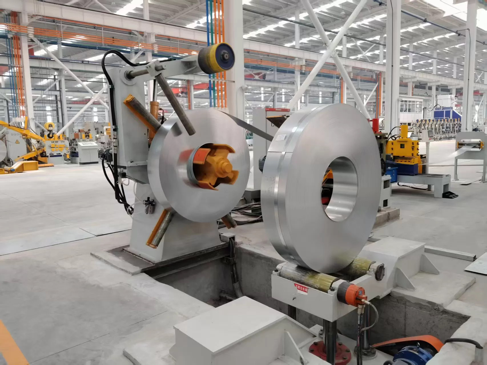
Engineering Selection Parameters for Pipe Mill Procurement
Specifying the correct equipment setup requires matching machine capabilities
with current and future strip processing needs. Mechanical failure often results
from matching lightweight pay-off stands with heavy production requirements.
Engineers and procurement teams should evaluate the following structural
criteria:
Maximum Payload Capacity: Engineering specifications focus
on heavy steel plate construction capable of supporting target coil weights,
typically ranging from 1.5 metric tons to 5 metric tons for manual setups.
Coil Inner Diameter (ID) Expansion Range: Mandrel expansion
stroke must accommodate standard mill coil cores (e.g., 460mm to 520mm) without
requiring custom adapters.
Maximum Outer Diameter (OD) Clearance: Floor-to-centerline
height must accommodate full-diameter coils with adequate safety clearance above
bed plates.
Maximum Strip Width: Mandrel segment length must fully
support the widest strip processed on the tube mill to prevent edge droop or
uneven tension.
Braking Torque Capability: Heavy-duty, spring-loaded
friction band or disc assemblies must deliver sufficient holding force to halt
full-diameter coils without overrunning.
Frequently Asked Questions
Q1: How does a manual decoiler maintain constant strip tension
without an electric drive motor?
A1: Tension is generated
mechanically by downstream processing equipment, such as a roll forming mill or
strip flattener, pulling the steel strip forward. The unpowered reel uses an
adjustable mechanical friction brake—utilizing spring-loaded pads or a brake
band on the main spindle shaft—to apply controlled resistance against this
pulling force. This back-tension keeps the metal strip flat, tight, and aligned
without motor control.
Q2: What is the maximum practical coil weight capacity for an
unpowered pay-off reel?
A2: Manual expansion and unpowered drag
setups operate efficiently with coil weights up to 3 to 5 metric tons. Beyond
this weight, the physical torque needed to turn the expansion screw increases,
and the pull force required from the downstream mill to overcome stationary coil
inertia can cause strip slippage or stretch thin gauge materials.
Q3: How do operators expand the mandrel segments inside a
coil?
A3: Operators use an external hand crank or mechanical wrench
attached to a lead screw on the front hub. Rotating this screw moves internal
wedge blocks along an inclined shaft. These wedges push the mandrel arc segments
outward simultaneously, locking the inside diameter of the coil firmly in
place.
Q4: What routine maintenance keeps mechanical payout units operating
smoothly?
A4: Maintenance relies on simple mechanical care:
regularly greasing the main spindle tapered roller bearings and internal
expansion wedge tracks via grease fittings, inspecting friction brake pads for
wear, and cleaning debris or mill scale off the sliding keyways on
side-adjustment bases.
Q5: Can an unpowered pay-off stand process surface-sensitive metals
like polished stainless steel or aluminum?
A5: Yes. To prevent
surface marking on the innermost wraps, the steel mandrel expanding jaws can be
equipped with polyurethane or rubber protective pads. Proper adjustment of the
friction brake prevents micro-slippage between wraps, keeping polished surfaces
intact throughout the run.
Engineering Custom Coil Entry Solutions for Your Mill
Selecting resilient material handling equipment directly impacts plant
uptime, operator safety, and downstream tube quality. Whether you are upgrading
an existing welded pipe mill, introducing custom profile tooling, or designing a
compact production line, integrating a robust manual decoiler into your tube
production line delivers long-term productivity and precise material feed
control.
Contact the SANSO technical engineering team to request an immediate inquiry,
review full mechanical engineering specifications, or consult on customized
entry-end configurations tailored to your precise coil width and weight
requirements.