Explore case studies, maintenance tips, and expert articles from our team.
Home>Blogs> ERW Tube Mill: The Complete Engineering & Process Guide
ERW Tube Mill: The Complete Engineering & Process Guide
2026-09-29
Electric Resistance Welded (ERW) pipe manufacturing balances metallurgy,
electrical induction physics, and continuous cold deformation mechanics. A
contemporary erw tube mill transforms raw hot-rolled or
cold-rolled slit coils into structural, automotive, or API-grade line pipes.
Achieving narrow dimensional tolerances, structural seam integrity, and minimal
material scrap requires precise control over each phase of the production line.
Engineering failures at the strip entry, forming passes, or weld junction
compound downstream, causing ovality errors, split seams, or premature tooling
degradation.
At SANSO, we design industrial-grade tube and pipe
production machinery to resolve these challenges. This technical overview breaks
down the multi-stage mechanical continuum of the ERW tube mill line, analyzes
the physics behind high-frequency welding, and outlines the engineering
parameters required to maximize continuous mill uptime.
1. The Strip Preparation and Entry Section
Continuous mill operation depends on uninterrupted raw material feed. The
entry section must flatten incoming steel strips, join the ends of successive
coils, and feed the forming units without stopping the breakdown stands.
Uncoiling and Peeling: Heavy-gauge coils are mounted on
dual-cone or expanding-mandrel uncoilers. Hydraulic snubbers and peeling blades
guide the strip lead end directly into the leveling unit without causing surface
scoring or edge deformation.
Precision Leveling and Flattening: Multi-roll flattens
remove coil set, cross-bow, and residual winding stresses. Accurate flatness
prior to breakdown prevents asymmetric tracking throughout the roll tooling
stands.
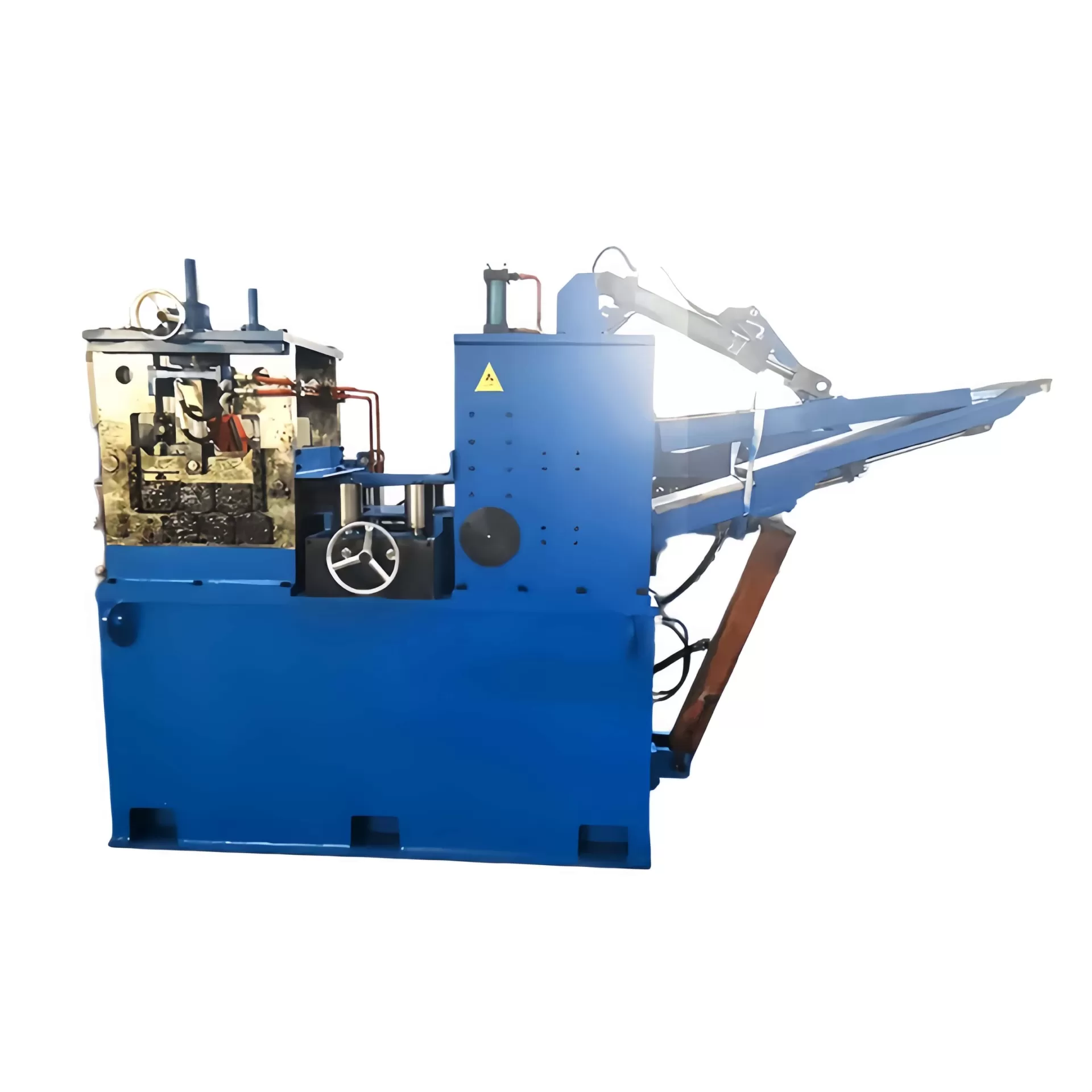
Shear and End Welding: To maintain continuous production,
the tail of the depleted coil is cropped square by a hydraulic shear and joined
to the lead of the incoming coil via automated TIG, plasma, or solid-state laser
welding.
Horizontal Spiral Accumulator: While the strip ends are
clamped and welded, the accumulator supplies buffered material to the continuous
forming mill. Strip-storage capacity determines the allowable cycle time for
end-joining operations without lowering the downstream mill velocity.
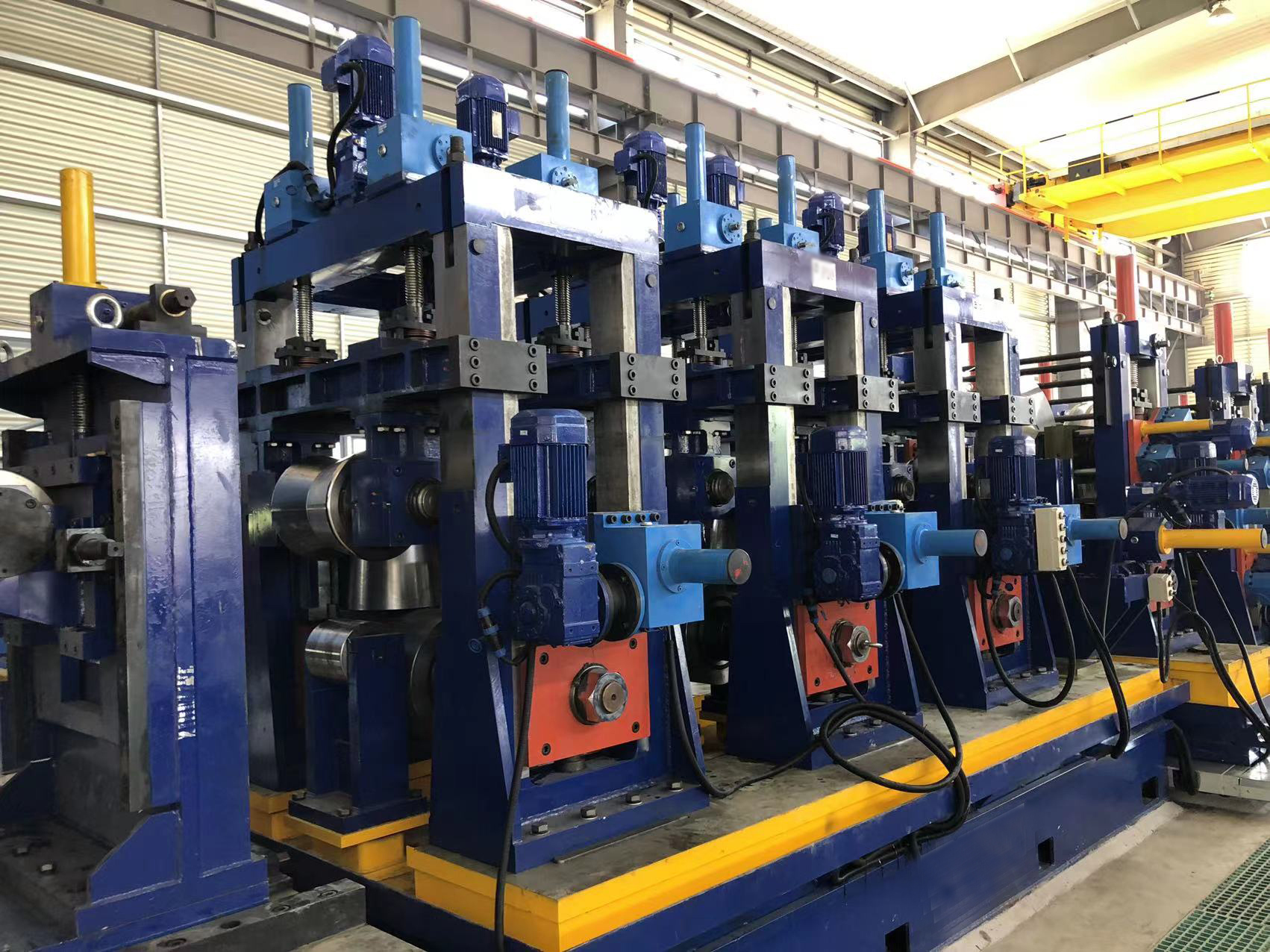
2. Cold Forming Mechanics: Breakdown and Fin-Pass Progression
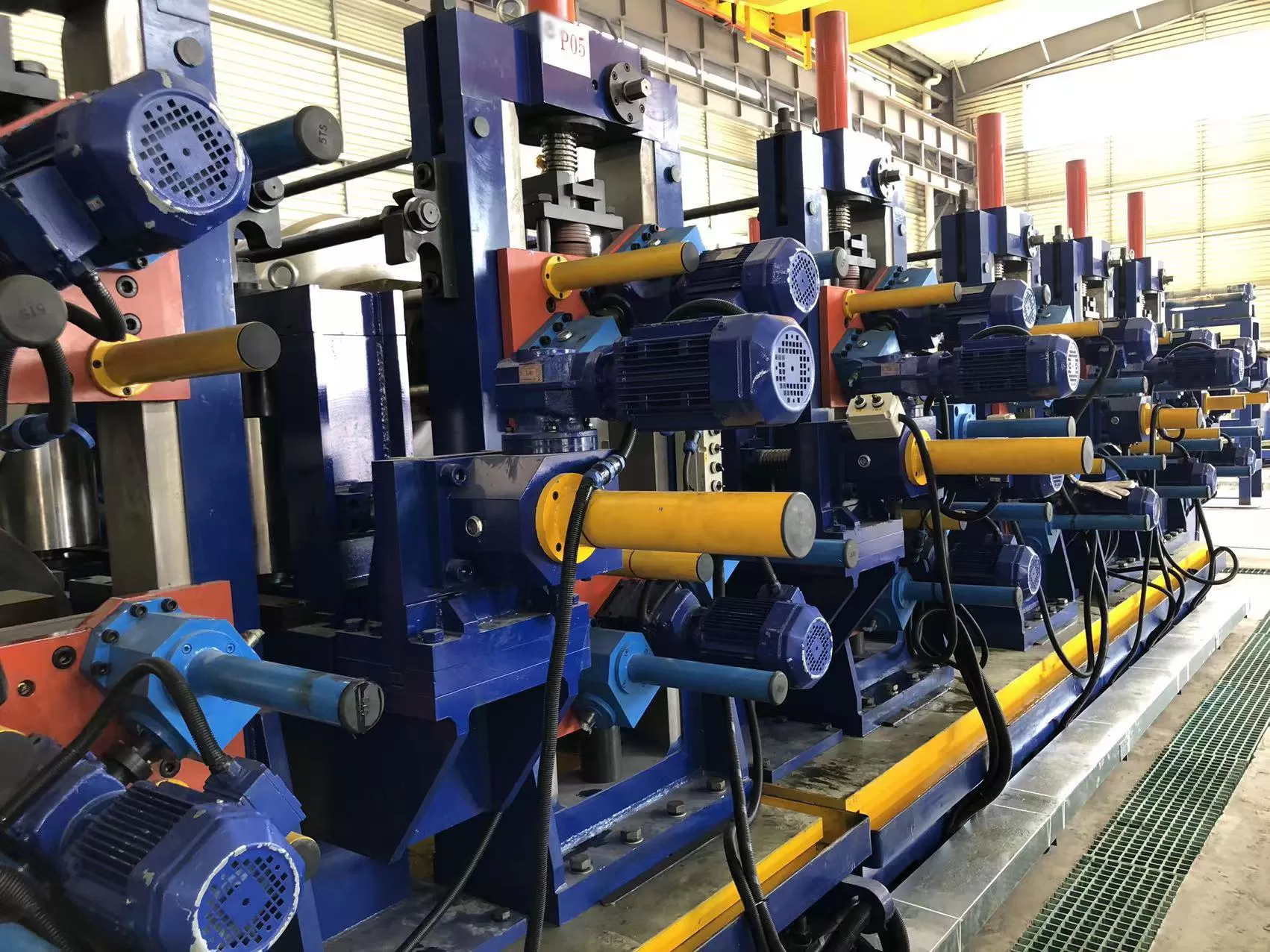
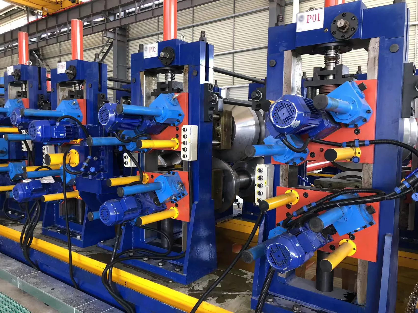
The forming section progressively bends the flat strip into an open-seam
round tube through cold roll forming. This section is divided into breakdown and
fin-pass zones to prevent edge stretching, oil-canning, and edge buckling.
Breakdown Section (Rough Forming)
Initial deformation relies on horizontal driven stands paired with vertical
idle side-rolls. Advanced mills often employ W-forming or cage-forming
configurations:
Driven Breakdown Stands: Uniformly curve the center section
of the strip while keeping the outer edges straight, mitigating differential
elongation along the strip axis.
Cage Forming Systems: Replace fixed-radius tooling with
clusters of adjustable small rolls, enabling continuous edge guidance, reducing
roll changeover time, and minimizing localized residual stress.
Fin-Pass Section (Precision Edge Forming)
The transition from a 'U' shape to an open cylindrical 'O' shape happens
within the fin-pass stands. The rolls feature an integrated central blade or
fin:
Edge Coining and Conditioning: The fin blades guide the
strip edges, burnish strip seams, and set the correct approach angle ($2^\circ$
to $7^\circ$) into the welding apex.
Circumferential Compression: The fin-pass rolls control
perimeter dimensions, ensuring edge alignment (preventing high-low mismatches)
right before induction heating.
3. High-Frequency Welding and Seam Conditioning
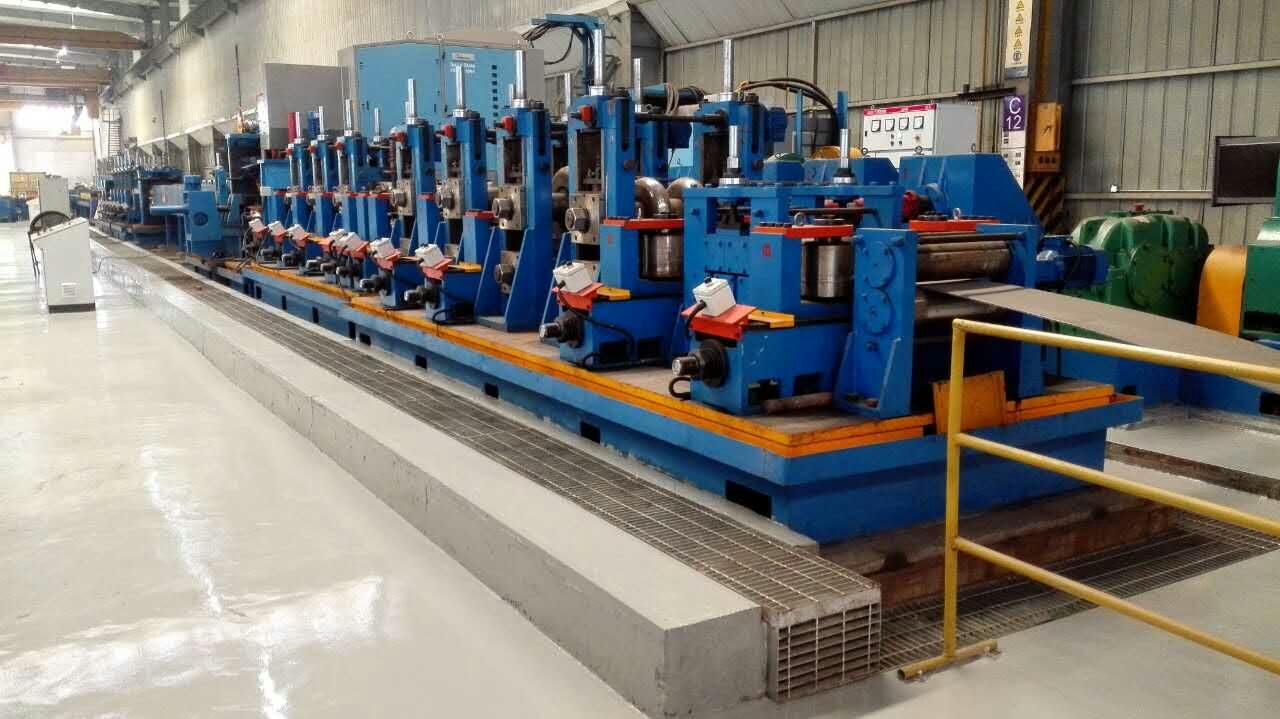
The performance of an erw tube mill centers on the weld
junction. Modern mills predominantly employ High-Frequency Induction (HFI)
welding rather than contact conduction tips to prevent surface burning and
mechanical contact wear.
The Physics of High-Frequency Induction Welding
Welding current typically cycles between 200 kHz and 450 kHz. At these high
frequencies, two fundamental electromagnetic phenomena govern the thermal
profile:
Skin Effect: Current concentrates on the extreme outer
periphery of the strip edge, restricting thermal dispersion into the parent
metal.
Proximity Effect: The current paths along opposing strip
edges attract each other, concentrating heat at the convergence apex immediately
prior to the squeeze point.
The Impeder Core: Positioned internally beneath the weld
point, a water-cooled ferrite impeder increases the inductive impedance of the
tube interior. This concentrates the magnetic flux through the open weld seam,
raising electrical efficiency and reducing input power requirements.
Forging and Flash Removal
Once the strip edges reach forging temperature ($1350^\circ\text{C}$ to
$1450^\circ\text{C}$ for carbon steel), heavy-duty squeeze rolls apply radial
pressure, expelling molten oxides, liquid slag, and impurities from the
joint.
Solid-Phase Bond: The expelled materials form the outer
diameter (OD) and inner diameter (ID) weld flash (bead), leaving a pure,
solid-state grain boundary weld across the seam.
In-Line Scarfing: Rigid OD carbide inserts trim the
external weld flash flush with the tube contour. Critical-spec industrial tubes
also use mandrel-supported internal ID scarfers to remove the root bead,
preventing flow turbulence or structural stress points.
Seam Normalizing: The rapid heating and quenching cycle
forms a hard, brittle martensitic/bainitic heat-affected zone (HAZ).
Medium-frequency inductive post-weld heat treatment (PWHT) heats the seam to
normalizing temperatures ($880^\circ\text{C}$ to $950^\circ\text{C}$),
recrystallizing the grain structure to match parent metal toughness and
ductility.
4. Sizing, Profile Transformation, and Straightening
Following weld seam air-cooling and emulsified water-quench cycles, the
closed tube passes into the sizing mill to achieve finished dimensional
tolerances, roundness, and specified cross-sections.
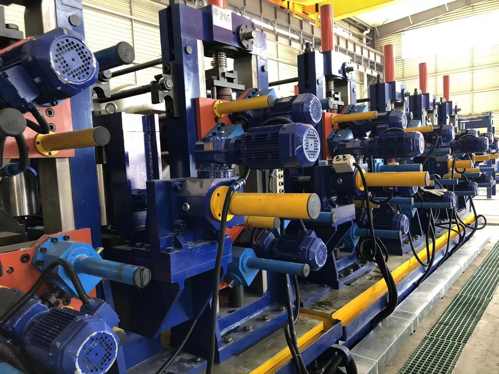
Precision Sizing Passes: Multiple driven two-roll or
four-roll sizing stands gradually compress the tube diameter by 1% to 3%. This
cold-working process corrects weld-induced shrinkage distortions and ensures
exact outer-diameter tolerances.
Turk's Head Units and Profile Shaping: If the end product
requires square, rectangular, oval, or flat-oval profiles, the round mother tube
passes through four-roll multi-axis Turk's Head units. These rolls reshape the
cross-section without requiring welded-seam repositioning, controlling corner
radiuses and wall thickness distribution.
Online Straightening: Integrated roll arrangements correct
bow, camber, and torsional twists, delivering straightness tolerances within
industry benchmarks (e.g., 1.0 mm to 1.5 mm per meter).
5. Automated Cut-Off and Secondary Finishing
Downstream finishing operations must maintain line velocity without causing
edge burrs, end-flaring, or ovality deformation at the pipe tips.
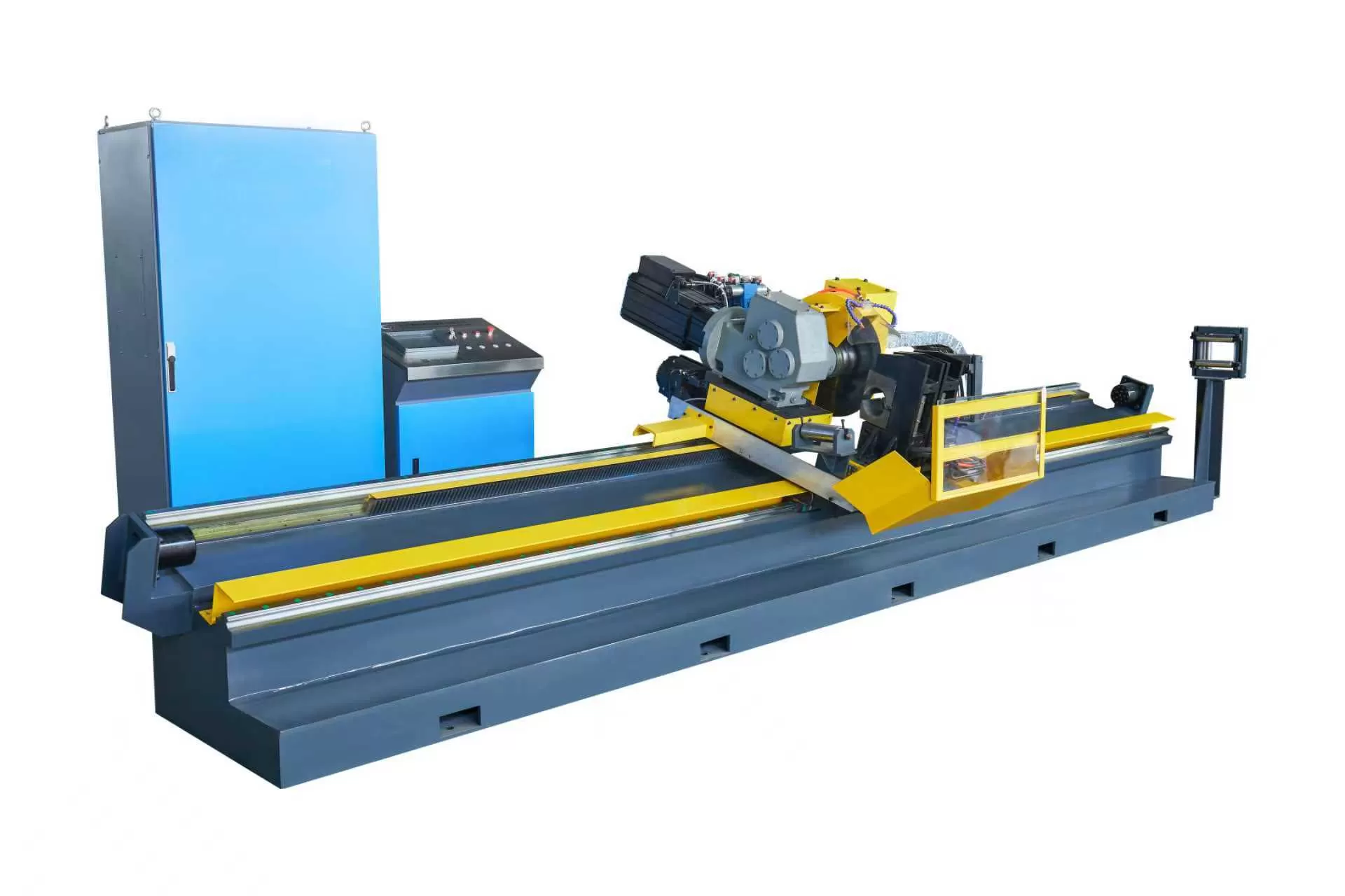
CNC Flying Cold Saw: Older friction saws heat-cut pipes via
abrasive friction, generating internal burrs, loud noise, and heat-affected
zones on the pipe ends. Modern lines feature CNC flying cold saws with
carbide-tipped circular blades. The carriage synchronizes dynamically with mill
velocity, cutting cleanly perpendicular to the axis with minimal burr
generation.
Non-Destructive Testing (NDT): Real-time in-line inspection
systems evaluate the weld seam. Encircling Eddy Current units and high-speed
Ultrasonic Testing (UT) arrays monitor internal laminations, weld gaps, and edge
mismatch, auto-marking defective segments for downstream rejection.
Facing, Hydro-Testing, and Packaging: High-specification
tubular goods pass to dual-head end-facing and chamfering machines, hydrostatic
leak-testing stations, and automated sorting and magnetic bundling
systems.
6. Core Operational Metrics: Efficiency, Tooling, and Yield Control
Choosing an industrial erw tube mill involves evaluating
mechanical rigidity and manufacturing economy. Key engineering metrics
include:
Yield Optimization: Scrap minimization is governed by the
consistency of strip-edge tracking in the breakdown stands and accurate cut-off
lengths. Advanced mill design limits startup scrap to under 1.5% of total
processed coil volume.
Tooling Wear Resistance: Roll tooling forged from
high-carbon, high-chromium die steels (such as Cr12MoV, D2, or SKD11) or
tungsten carbide inserts prevents galling, maintains precise contact geometry,
and maximizes production tonnage between regrinds.
Quick-Change Cassette Architecture: Downtime between
schedule shifts (round-to-square or size changes) is shortened using rafted or
cassette quick-change mill configurations, reducing mechanical changeover
windows from an entire shift to under 45 minutes.
Modern tube manufacturing demands high line speeds along with strict
metallurgical reliability. SANSO manufactures high-performance
ERW tube mill installations suited for thin-wall precision tubes, heavy-wall API
casing lines, and high-strength structural profiles.
Every SANSO tube mill integrates robust base mechanics with advanced
industrial automation. Featuring low-deflection mill stands, high-efficiency
solid-state HF welding circuits, automated scarfers, and digitally synchronized
flying cold cut-off units, SANSO systems ensure high productivity and consistent
pipe quality.
Upgrade Your Tube & Pipe Manufacturing Capabilities
Whether configuring a new turnkey ERW tube mill facility or optimizing the
speed, weld integrity, and roll longevity of an existing production line,
consult with the engineering team at SANSO. Contact our
technical sales office today to review custom machine specifications, tooling
profiles, and line proposals.
Frequently Asked Questions (FAQ)
What is the difference between ERW and HFW in tube manufacturing?
ERW (Electric Resistance Welding) is the broader classification encompassing
all resistance-based longitudinal welding. Historically, low-frequency
electrical contacts were used. HFW (High-Frequency Welding) is a modern
evolution of ERW that utilizes currents above 150 kHz, delivered via induction
or conduction. Today, the term "ERW tube mill" almost exclusively describes
automated mills utilizing high-frequency induction (HFIW) systems.
Why is weld seam normalizing critical for ERW pipes?
The rapid heating and quench cycle of the high-frequency weld process creates
a localized martensitic micro-structure in the weld seam and Heat-Affected Zone
(HAZ), which is hard and brittle. In-line seam normalizers use medium-frequency
induction coils to reheat this narrow band above the austenitizing temperature
($Ac_3$), homogenizing the grain boundary structure to achieve mechanical
strength and ductility equal to the parent material.
What causes weld-seam mismatch (high-low defects) in an ERW tube mill?
High-low defects typically stem from improper breakdown forming, inaccurate
fin blade thicknesses, uneven strip slit edges (burrs or edge camber), or worn
roll tooling bearings. Maintaining tight tolerances in the fin-pass roll stands
ensures edges align symmetrically at the apex within the squeeze rolls.
How does a flying cold saw compare to a conventional hot friction flying
saw?
Flying cold saws use tooth-geared, carbide-tipped or HSS circular blades
rotating at low speeds to cut cleanly through the pipe wall without thermal
degradation. In contrast, friction saws melt their way through steel using
toothless or hardened blades at high rotational velocities, leaving heavy
inner/outer burrs, noise levels above 100 dB, and heat-affected ends that
require secondary facing operations.
What parameters define the ideal V-angle for high-frequency welding?
The convergence angle of the open tube edges approaching the squeeze point
(the V-angle) should typically be held between $2^\circ$ and $7^\circ$. If the
V-angle is too wide, the electrical proximity effect is compromised, requiring
excessive weld power. If the angle is too narrow, pre-arcing and unstable weld
flashes occur, producing inclusions and cold-weld seam defects.