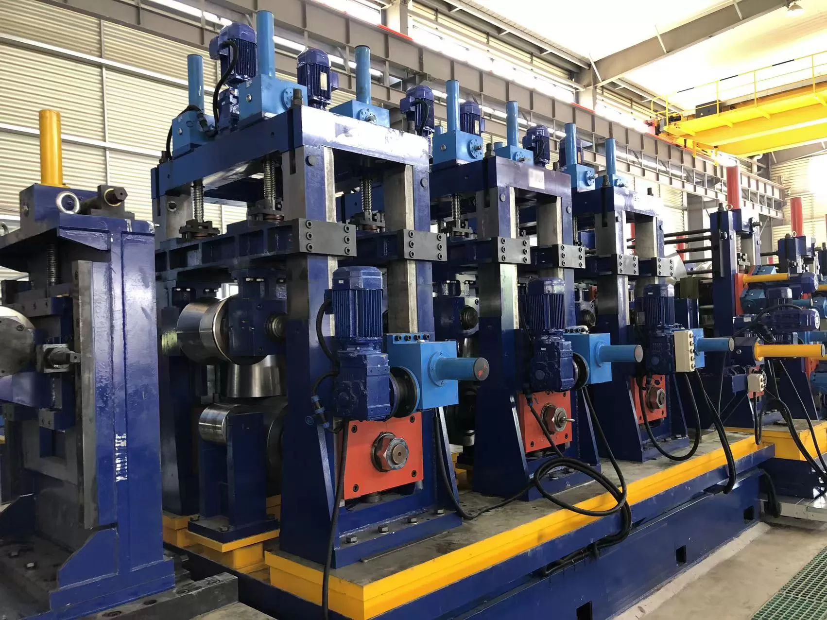
Tooling wear represents one of the largest hidden drains on tube and pipe
manufacturing margins. As high-strength low-alloy (HSLA) steels, advanced
high-strength steels (AHSS), and abrasive stainless alloys become industry
staples, standard tooling wears out faster than ever. An unexpected roll
changeover does not simply waste shop hours; it costs thousands of dollars per
line in lost tonnage, scrap material, and labor.
Most operations accept premature tooling wear as an unavoidable cost of doing
business. It is not. By moving away from reactive fixes and adopting disciplined
maintenance engineering, tube producers can double their roll life cycle. At
SANSO, our tooling engineers regularly review worn tooling sets and find that
30% to 40% of roll tooling expenditure can be saved without sacrificing tube
surface quality or line speed.
This guide breaks down the engineering principles, material selections, and
shop-floor protocols needed to extend the operational life of your tube mill
rolls through 2026 and beyond.
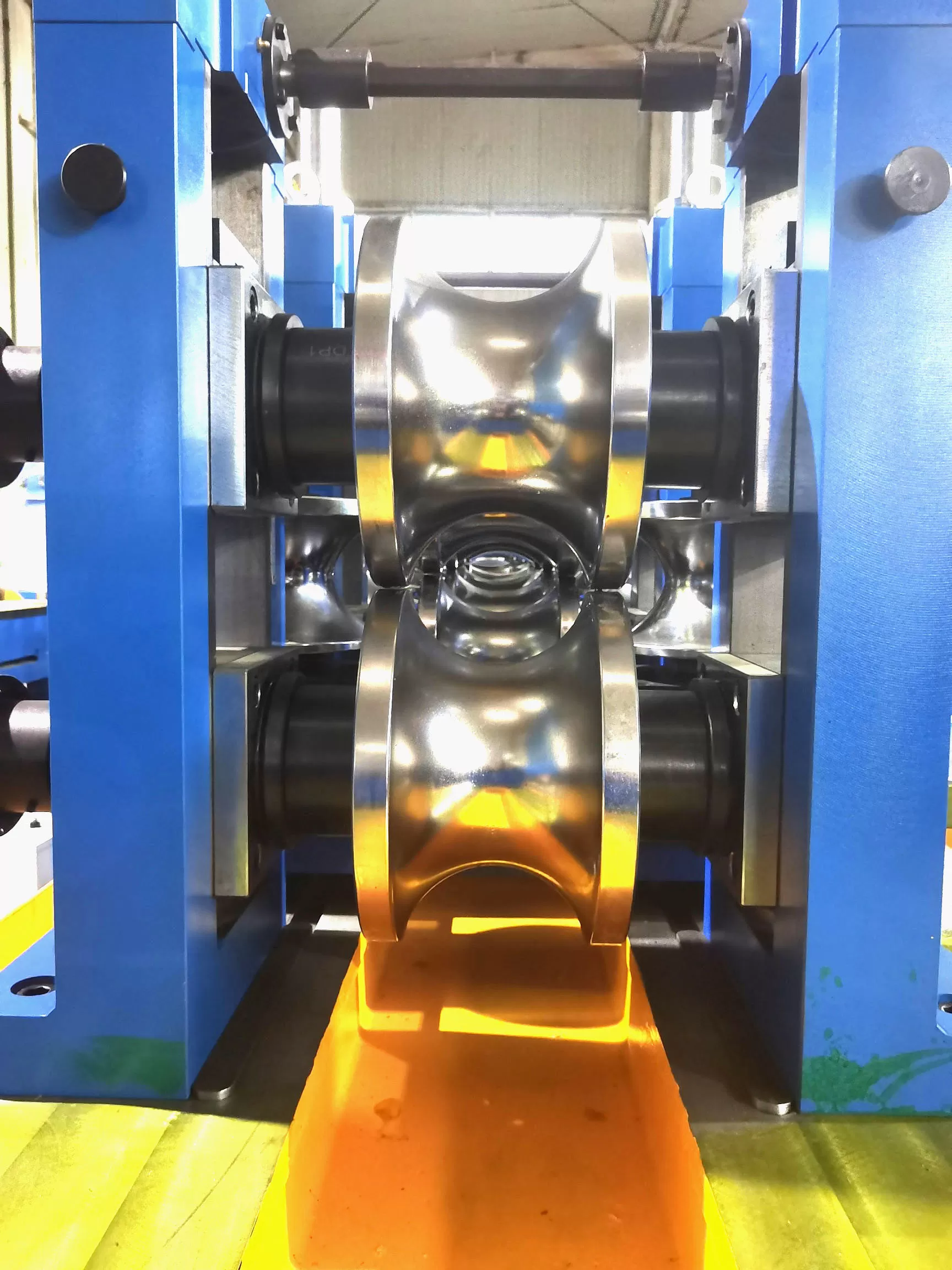
1. Material Metallurgy: Stop Using a Single Steel Grade for Every Pass
The traditional approach of building an entire roll set out of basic AISI D2
(Cr12MoV) is outdated. Every section of a tube mill subjects the tooling to
entirely different mechanical, thermal, and abrasive stresses. A single tool
steel grade cannot perform well across every stage.
Extending roll life begins by matching the alloy chemistry to the specific
work zone on the mill:
Breakdown Passes: These stands absorb heavy entry shock,
high mechanical torque, and intense bending loads. Standard D2 often chips at
the roll flanges under this stress. Using shock-resistant, high-toughness tool
steels such as modified AISI S7 or 8% chromium cold-work steels prevents
premature edge fracturing.
Fin Passes: The fin pass experiences abrasive strip-edge
rubbing and high localized unit pressure on the fin blade. Powder metallurgy
(PM) tool steels like CPM 10V or CPM M4 deliver uniform carbide distributions
that outlast conventional ingot-cast D2 by a factor of three.
Welding / Squeeze Rolls: High-frequency ERW welding exposes
squeeze rolls to intense radiant heat, scale pick-up, and continuous water
flushing. Premium hot-work tool steels like vacuum-degassed AISI H13 or
specialized non-magnetic alloys prevent inductive heating and resist thermal
fatigue cracking.
Sizing Passes: Sizing requires maximum dimensional
stability and wear resistance under high continuous contact pressure. Fine-grain
cold-work steels, high-vanadium powder alloys, or tungsten carbide inserts
ensure your profiles hold tight OD tolerances over millions of linear
meters.
Heat treatment quality dictates your baseline performance. Vacuum hardening
combined with triple tempering stabilizes the steel structure. Furthermore,
specifying deep cryogenic treatment (-196°C) between tempers transforms retained
austenite into hard martensite, bringing retained austenite levels below 5%.
This step eliminates delayed microcracking under cyclic loading.
2. Advanced Surface Engineering: Beyond Conventional Chrome
Surface galling remains a constant threat when producing stainless steel,
titanium, or pre-galvanized mechanical tubing. Once strip material welds to the
roll surface, the resulting friction marks scrap whole bundles of tubing and
ruins the pass profile.
While hard chrome plating was the historical standard, micro-cracks inherent
to heavy chrome deposits allow corrosive mill emulsions to attack the substrate
steel. Modern physical vapor deposition (PVD) coatings create a superior, dense
metallurgical barrier against abrasive and adhesive wear.
| Coating Technology | Microhardness (HV 0.05) | Friction Coeff. (Dry vs Steel) | Max Temp (°C) | Best Production Fit |
|---|
| Hard Chrome Plating | 850 – 1,000 | 0.45 – 0.50 | 400 | General carbon steel (Legacy lines) |
| Titanium Nitride (TiN) | 2,200 – 2,400 | 0.40 | 500 | Light forming, decorative tube lines |
| Titanium Aluminum Nitride (TiAlN) | 3,000 – 3,300 | 0.30 – 0.35 | 800 | High-speed ERW, heavy-wall breakdown |
| Chromium Nitride (CrN) | 1,750 – 2,050 | 0.30 | 700 | Galvanized tubing (Resists zinc pick-up) |
| Diamond-Like Carbon (DLC) | 2,500 – 4,000 | 0.10 – 0.15 | 350 | Austenitic stainless, non-ferrous lines |
When implementing coatings, ensure the core substrate has sufficient hardness
(minimum 58–60 HRC). If the base steel yields under mechanical pressure, thin
PVD films will crack like eggshells. Specialized suppliers like SANSO utilize
engineered substrate pre-treatments to ensure PVD layers adhere cleanly
throughout long production runs.
3. Precision Alignment: Eliminate Mechanical Misalignment
More than half of all damaged tube mill rolls do not wear out from natural
friction; they fail because of mill misalignment. A stand out of parallel by
just 0.05 mm forces the strip against one side of the roll pass, generating
uneven side thrust, high heat, and localized galling.
To eliminate mechanical binding, apply the following setup rules across your
mill stands:
Ditch the Steel Rulers: Mechanical straightedges and dial
indicators mounted on dirty housings cannot maintain precision over a 30-meter
base. Implement laser alignment systems to verify roll spindle parallelism,
center-line runout, and vertical pass-line levels.
Control Arbor End-Play: Worn shaft bearings allow arbors to
float axially under load. Check arbor thrust clearances on every shift. Axial
shaft movement must never exceed 0.015 mm on sizing and fin pass stands.
Manage Peripheral Speed Mismatch: In deep breakdown passes,
the roll diameter at the pass root is significantly smaller than at the outer
flanges. Because both sections turn on the same arbor at the same RPM, the
surface speed at the flange is much faster than at the root. This speed
differential scuffs the tube strip and scrubs the roll shoulders. Compensate for
this by utilizing driven driven-roll steps, free-wheeling flange inserts, or
driven side rolls.
4. Coolant Chemistry and Micro-Filtration Control
Mill operators frequently look at coolant only as a way to keep rolls from
overheating. In reality, coolant quality directly controls both thermal fatigue
and abrasive wear rates on every roll profile.
Cooling mistakes usually show up in two distinct operational areas:
Thermal Shock in Squeeze Rolls
ERW squeeze rolls operate directly beside the weld pool. Flooding one side of
the squeeze roll while leaving the adjacent flange dry causes steep thermal
gradients. The metal expands and contracts hundreds of times per minute,
triggering spider-web surface fractures known as heat checks. Position coolant
manifolds to deliver balanced, uninterrupted, low-pressure, high-volume flow
around the complete contact circumference of the roll.
The Danger of Abrasive Slurry
As the strip passes through forming and seam preparation, sharp scale
particles and iron fines break loose and wash into the coolant sump. If your
coolant system relies on simple gravity settling tanks, the pump recirculates
those hard iron fines directly back into the roll-to-strip interface. The
coolant stops acting like a lubricant and turns into an abrasive lapping
compound.
Upgrade your coolant management using these parameters:
Install high-intensity magnetic separators followed by bag filters rated to
20 microns or finer.
Maintain synthetic or semi-synthetic emulsion concentration between 8% and
12% using a daily calibrated refractometer.
Monitor coolant tank temperatures. Keep operational fluids between 25°C and
35°C. Emulsions operating above 45°C lose lubricity and accelerate bacterial
breakdown.
5. The Preemptive Regrind Rule: Repair Before Failure
The most destructive habit on a tube line is running tooling until the roll
profile fails inspection or scratches the finished tube. Waiting for visible
product defects means the roll surface has already developed deep micro-cracks
below the contact skin.
When you wait too long, a toolmaker must grind off 0.5 mm to 1.0 mm of
valuable tool steel to clean out the micro-fissures. Doing this two or three
times reduces the diameter past minimum operational tolerance, turning an
expensive tool into scrap metal.
Implement the "light and frequent" redress principle:
Track production through each pass by total linear meters run, not merely by
working shifts or days.
Pull tooling sets at predetermined tonnage intervals (for example, every
250,000 meters on carbon steel or 100,000 meters on AHSS).
At these thresholds, surface microcracks rarely exceed 0.05 mm to 0.08 mm in
depth. A light skim cut on a CNC grinding machine restores original geometry
while removing minimal base steel.
Always perform magnetic particle inspection (MPI) or dye penetrant testing
after regrinding to confirm every micro-fissure is gone before storing or
reusing the tooling.
Insist on CNC-controlled profile grinders to preserve exact pass contours.
Hand-polishing or manual lathe touch-ups change the intended bend radii, ruin
the designed edge elongation, and push destructive forming stresses onto
adjacent stands downstream.
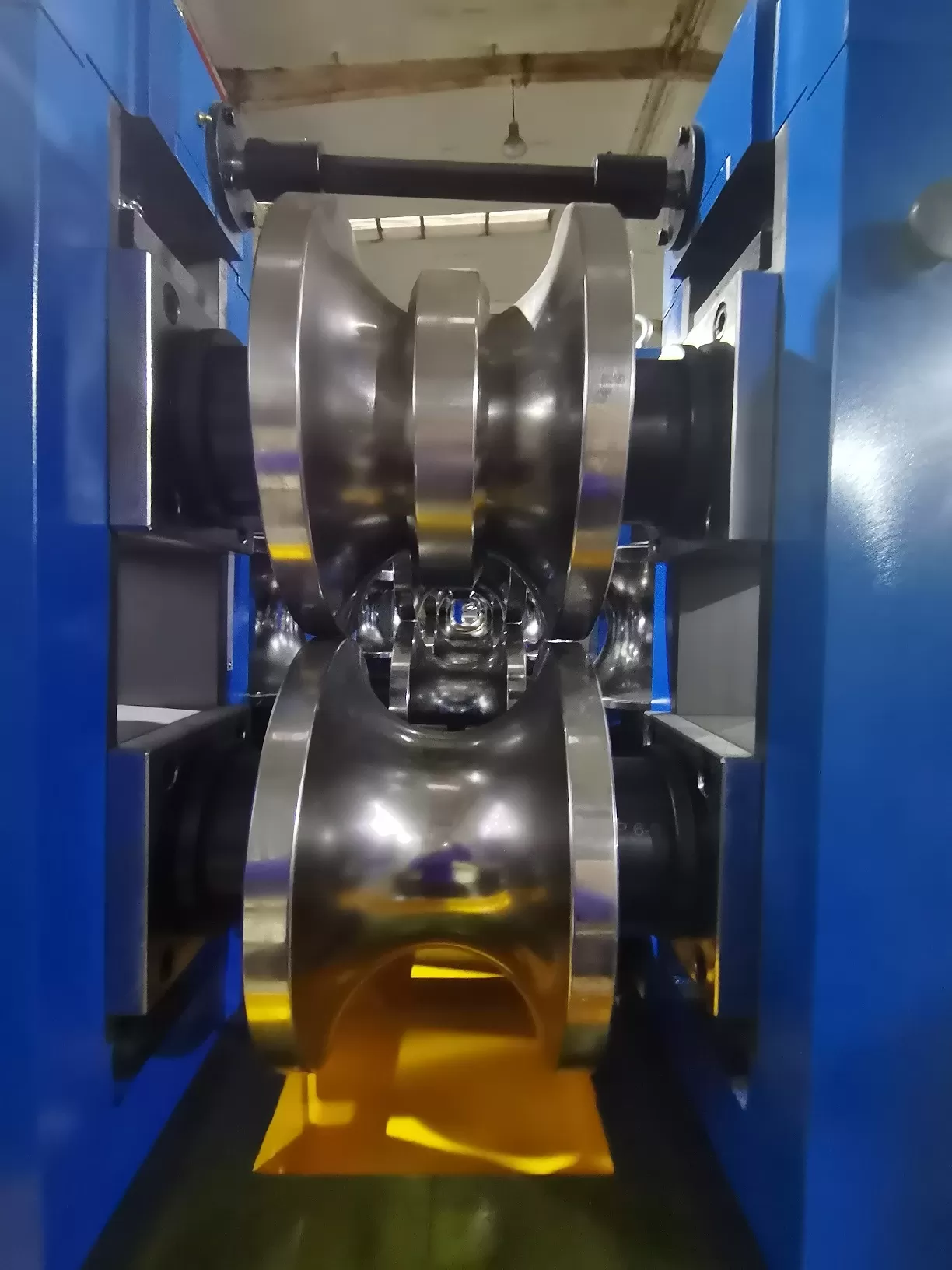
6. Downloadable Maintenance and Inspection Checklist
Reliable roll life requires steady shop-floor routines. Use this reference
table during shift audits to catch mechanical wear before it damages your roll
tooling.
| Frequency | Inspection Point | Operating Standard | Action on Deviation |
|---|
| Every Shift | Coolant nozzle direction & pressure | Continuous flood over contact zone; zero dry spots | Clear clogged nozzles; verify line pump pressure |
| Every Shift | Roll flange gap measurement | Within ±0.02 mm of setup chart values | Re-shim arbors; inspect adjusting screw backlash |
| Weekly | Arbor runout & axial float | Total indicator reading (TIR) < 0.015 mm | Replace spindle bearings; machine worn lock collars |
| Weekly | Coolant emulsion solids & pH | Solids < 20μm; pH between 8.8 and 9.4 | Clean magnetic drums; recharge fluid emulsion |
| Monthly | Profile optical / contour trace | Radius deviation ≤ 0.04 mm from master CAD | Schedule for light CNC profile redress |
| Monthly | Non-destructive crack testing (NDT) | Zero visible stress cracks under MPI examination | Light-cut skim grinding to bottom of crack depth |
Need a clean version for your shop floor? Download our printable PDF:
Tube Mill Roll Maintenance & Wear Diagnostic Matrix 2026 to
guide your maintenance crews through root-cause wear analysis.
Frequently Asked Questions
Q1: How often should tube mill rolls undergo
regrinding?
A1: Regrind intervals depend on strip chemistry, wall
thickness, and mill speed. For standard structural carbon steel, plan a light
skim redress every 200,000 to 300,000 linear meters. When running abrasive HSLA
or stainless alloys, inspect and lightly regrind rolls every 80,000 to 120,000
meters. Never run tooling until the pipe shows surface defects, as deep stress
cracking will require heavy stock removal.
Q2: Why do ERW squeeze rolls develop spider-web surface
cracking?
A2: Spider-web cracking, known as heat checking, stems
from thermal shock. High-frequency welding generates temperatures above 1,300°C
at the tube seam, while the roll base gets sprayed with room-temperature water.
This sharp cycle of heating and cooling forces the outer metal grain to expand
and contract rapidly. Using H13 tool steel, optimizing non-magnetic roll
holders, and establishing balanced coolant coverage prevents this wear.
Q3: What is the optimal coolant filtration level for roll forming
dies?
A3: Keep coolant filtered down to 20 microns or finer.
Unfiltered mill scale, metal slivers, and iron fines recirculate through the
nozzles and turn your coolant stream into an abrasive compound. Combining
high-gauss magnetic separators with high-capacity continuous paper or bag
filters protects your roll finishes and stops strip scoring.
Q4: Can we coat reground rolls without stripping the old
coating?
A4: No. Applying a new PVD or thin-film coating over a
partially worn surface leads to poor adhesion, uneven coating thickness, and
early flaking. When a coated roll needs redressing, chemical or electrochemical
stripping must remove the remaining coating down to the raw steel. Grind and
polish the profile back to master tolerances, then reapply the PVD treatment
onto clean, virgin tool steel.
Q5: When should a plant transition from D2 tool steel to powder
metallurgy (CPM)?
A5: Transition to powder metallurgy steels when
abrasive wear forces roll changes more than twice a month, or when running
high-tensile materials like AHSS and ferrite-free stainless. While CPM tooling
costs 30% to 50% more upfront than standard D2, it eliminates coarse carbide
clusters. It regularly delivers three to five times longer wear life, making it
significantly cheaper per ton of finished tube.
Protect Your Tooling Investment
Running a competitive tube plant requires minimizing unexpected downtime.
Extending the lifespan of your tube mill rolls is not an impossible puzzle. It
simply demands the right base metals, proper stand alignment, clean coolant, and
disciplined, early redressing schedules.
Are premature roll wear, flange chipping, or profile marking cutting into
your plant's margins? The engineering team at SANSO designs, manufactures, and
re-engineers high-durability tube mill rolls, custom pass profiles, and
wear-resistant coatings built for tough production schedules.
Contact SANSO Tooling Engineers today to request a comprehensive Pass Design &
Tooling Wear Audit, or call our application desk to evaluate your line
parameters.