Modern tubular manufacturing demands uncompromising mechanical stability,
where an integrated tube mill line transforms flat-rolled steel coils into
structural, automotive, and fluid-handling profiles. Precision cold roll
forming, high-frequency induction welding (HFIW), weld bead scarfing, thermal
seam annealing, and multi-axis sizing must synchronize seamlessly. Achieving
microstructural integrity across diverse wall-thickness-to-diameter ($D/t$)
ratios requires deep operational comprehension of plastic strip deformation,
high-frequency electromagnetic field concentrations, and closed-loop kinematic
control.
Strip Preparation, Accumulation, and Continuous Entry Mechanics
Process stability along the mill axis depends fundamentally on the
continuous, uniform delivery of skelp steel. Entry-section dynamics determine
whether downstream forming stands maintain stable roll-contact pressures or
experience destructive tension fluctuations.
Uncoiling and Strip End Joining
Raw steel coils, typically hot-rolled or cold-rolled carbon steel, low-alloy
structural steel, or stainless alloys, exhibit varying degrees of residual
stress, coil set, and edge camber. The decoiler must feature hydraulic expansion
mandrels equipped with regenerative pneumatic or electric back-tension braking
to prevent loose loops and edge damage. Straightener and flattener units
immediately downstream utilize staggered work rolls to reverse residual plastic
curvature, delivering a dead-flat strip to the shear and end welder.
To eliminate mill shutdowns during coil changeover, hydraulic shear and end
welders execute precise perpendicular edge cropping followed by automated TIG,
plasma, or solid-state laser butt welding. Weld seam profiling must maintain
strip thickness parity without excessive bead reinforcement that could damage
tooling passes downline.
Horizontal and Spiral Accumulation Dynamics
Continuous line operation requires an intermediate reserve of strip material
while the upstream coil is spliced. Modern installations prefer horizontal
spiral accumulators over traditional vertical pit or loop tower systems due to
their reduced factory footprint and lower surface scuffing tendencies. Inside
the accumulator, the strip enters tangentially and forms concentric expanding
spirals supported by polyurethane-coated guide rollers.
Variable-speed pinch rolls: Match entry delivery rates up
to three times operating mill velocity during refill cycles.
Centering guides: Active edge sensors dynamically realign
cambered strip edges, preventing lateral strip migration prior to breakdown
entry.
Back-tension governors: Maintain stable strip hold-back
torque, eliminating shock loads that trigger premature bearing degradation in
early breakdown roll stands.
Roll Forming Kinematics: Breakdown and Fin Pass Mechanics
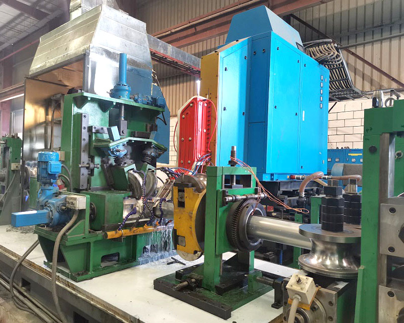
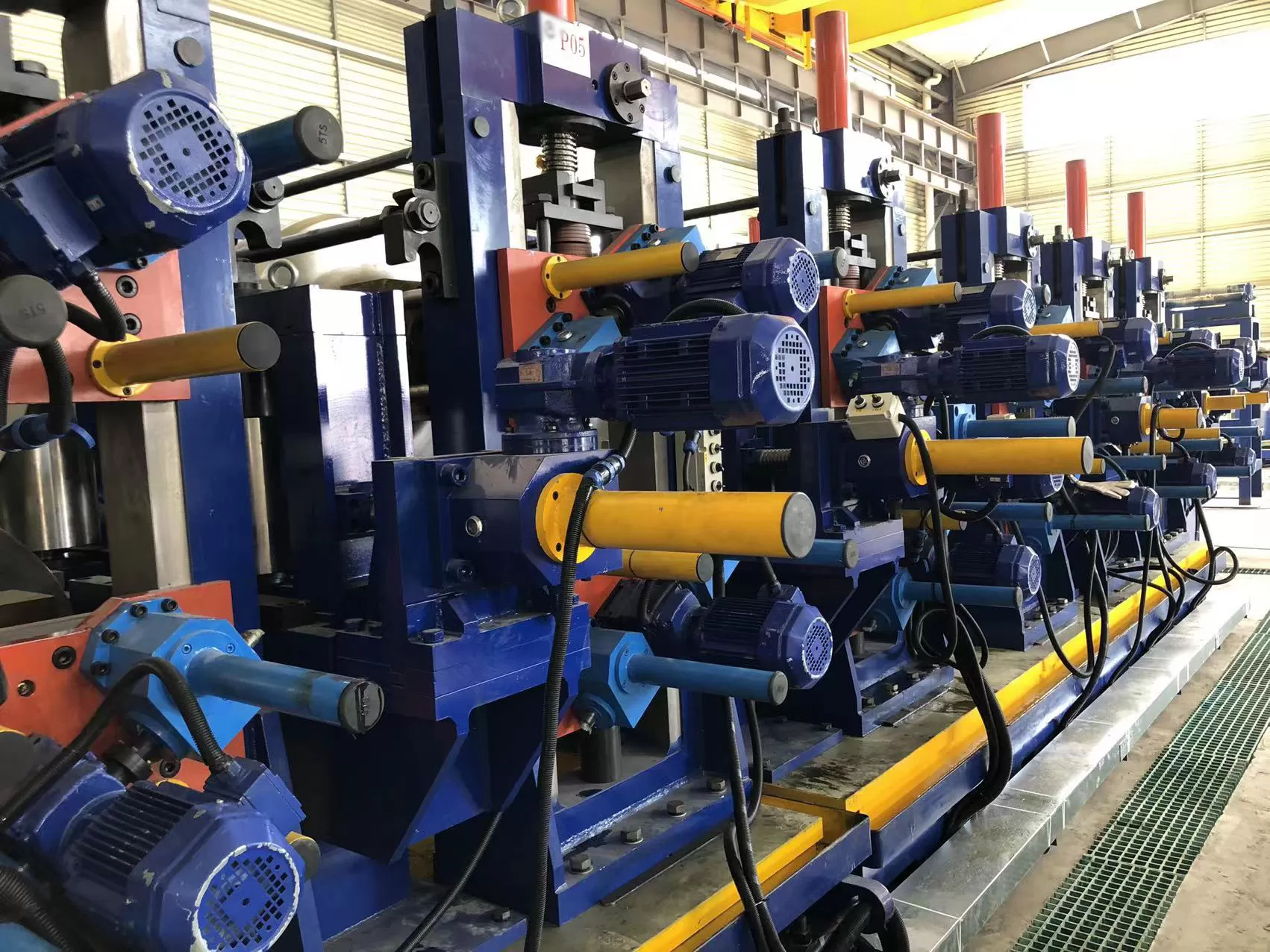
Within an automated tube mill line, strip deformation begins in the forming
section, converting flat strip into an open cylindrical hollow through
progressive cold roll passes. Tooling engineers balance strain hardening against
edge stretch to prevent wavy edge defects and transverse buckling.
Breakdown Pass Geometry: Conventional vs. W-Forming
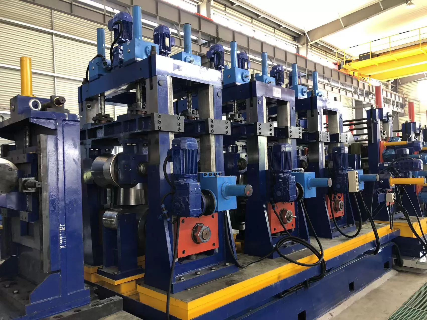
The initial forming zone consists of driven breakdown stands alternating with
idle side-roll clusters. In standard radius forming, concave top rolls and
convex bottom rolls bend the strip center downward. When processing
high-strength low-alloy (HSLA) materials or thin-walled tubing, standard passes
tend to impart severe localized stretching along the strip edges, resulting in
oil-canning and uneven seam alignment.
Advanced lines implement the W-forming technique, where the breakdown passes
impart an initial reverse curve at the strip center while up-curving the outer
edges. This distributes transverse bending stresses evenly across the entire
strip cross-section. The neutral axis of the steel remains stable, significantly
cutting longitudinal edge strain and enabling tighter tolerance control on
downline fin passes.
Fin Pass Progression and Edge Conditioning
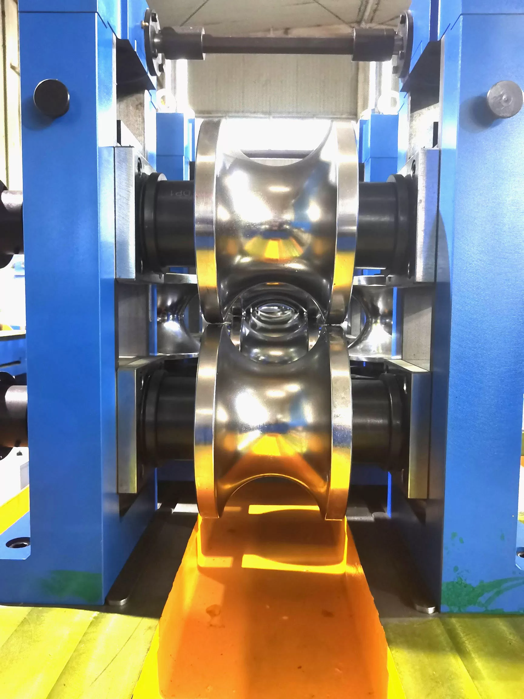
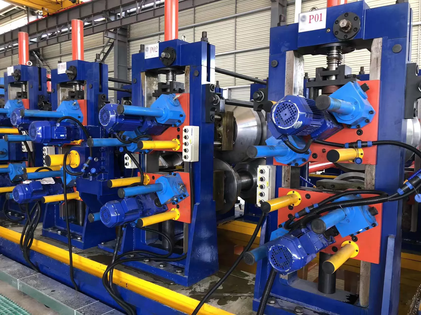
Following the breakdown section, the semi-closed profile enters the fin pass
stands. Fin rolls feature a central protruding tongue (fin) that rides inside
the open seam gap. These passes fulfill critical mechanical functions:
They complete the circumferential curvature of the tube corners and upper
shoulders.
The fin blade mechanically conditions and burnishes the strip edges,
squaring them to ensure parallel mating faces at the welding apex.
They calibrate the overall tube girth, ensuring precise circumference before
the squeeze rolls compress the strip edges into the weld plane.
Structural rigidity during this phase is paramount. Roll deflection caused by
high-yield materials causes dimensional drift, which is why incorporating SANSO
heavy-duty mill housing assemblies with double-eccentric screw-down adjustments
and anti-backlash gearing ensures sub-millimeter axial roll alignment under
severe dynamic loads.
High-Frequency Welding Physics and Seam Metallurgy
High-frequency electric resistance welding (ERW) and high-frequency induction
welding (HFIW) rely on electromagnetic induction to heat the mating strip edges
to forge-welding temperatures (1350°C to 1450°C for carbon steels) without
melting the entire wall cross-section.
Skin Effect, Proximity Effect, and V-Angle Geometry
High-frequency alternating current, typically ranging between 150 kHz and 400
kHz, behaves according to distinct electromagnetic phenomena:
Skin Effect: Current concentrates along the outermost
peripheral layer of the conductor, with depth inversely proportional to the
square root of the frequency and magnetic permeability.
Proximity Effect: When the two converging strip edges
approach the weld point at an acute angle (the weld V-angle, typically set
between 2° and 6°), the currents flowing in opposite directions attract each
other, concentrating heat purely along the opposing joint faces.
Impeders placed inside the tube direct electromagnetic flux toward the seam
edges by increasing the inductive reactance of the parallel electrical paths
around the tube backwall. Constructed from high-permeability, low-loss ferrite
cores encased in heat-resistant epoxy or silicon-carbide jackets, impeders
require constant, high-pressure internal water cooling to prevent operating
temperatures from crossing the Curie point, where magnetic permeability drops to
unity.
Squeeze Stand Mechanics and Forge Upset Control
The squeeze roll unit applies controlled radial forging forces immediately as
the edges converge at the apex. Proper welding does not rely on molten casting;
it requires solid-phase forge consolidation. Hydraulic or mechanical squeeze
rolls force softened metal together, expelling molten oxides, non-metallic
inclusions, and liquid films into the external and internal upset beads (weld
flash).
Forging force balance must remain uniform. Insufficient squeeze force results
in cold-weld defects, penetrators, and incomplete fusion along the centerline.
Excessive force expels too much hot metal, causing excessive thinning of the
heat-affected zone (HAZ), steep fiber-flow angles, and reduced transverse impact
toughness.
Inline Scarfing Systems
Immediately after the squeeze rolls, the external and internal upset beads
must be planed flush with the tube profile while the steel remains ductile:
OD Scarfing: Heavy-duty, carbide-tipped scarfing inserts
mounted on micro-adjustable tool holders trim the outer bead. Modern systems
incorporate automatic tool wear monitoring and quick-indexing rotary rings.
ID Scarfing: An internal cantilevered mandrel, held axially
by tow-ropes anchored upstream in the fin section, supports a hydraulic or
spring-loaded cutting head. Internal scarfing mandates integrated ring cutters,
impeder housing passes, and ferrite channels engineered to resist
vibration-induced tool chatter.
Thermal Processing: Inline Weld Seam Annealing
Rapid thermal cycles inherent in high-frequency welding create localized
microstructural alterations. As forged weld zones cool quickly through
conductive heat transfer into the cold adjacent pipe body, hard, brittle
transformation products—such as martensite and coarse bainite—develop within the
weld seam and narrow HAZ.
To restore mechanical ductility and equalize mechanical properties across the
parent metal and joint, modern production lines deploy intermediate-frequency
induction seam annealers (1 kHz to 3 kHz). Annealing inductors follow the seam
trajectory, reheating the weld zone above the upper transformation temperature
($Ac_3$, typically 880°C to 950°C). This allows recrystallization into a
fine-grained, equiaxed ferrite-pearlite matrix.
Controlled cooling setups feature extended air-cooling runout sections
followed by indirect water-quench cascades. Precise infrared optical pyrometers
provide closed-loop control to the induction power generators, guaranteeing
consistent grain refinement throughout continuous shifts without introducing
thermal shock distortion.
Dimensional Sizing, Profile Shaping, and Straightening
Downstream from the quenching bath, the tube mill line utilizes a multi-stand
sizing sequence to achieve definitive cross-sectional tolerances, roundness, and
straightness. Sizing stands impart a 1.5% to 3.0% total reduction in diameter,
compressing the tube through circular roll passes to eliminate out-of-round
conditions stemming from non-uniform thermal contraction during welding.
Round-to-Square and Structural Profile Transformation
When producing hollow structural sections (HSS), square, rectangular, or
complex architectural tubing, mills employ two structural shaping
philosophies:
Direct Forming: The flat strip is bent directly into
rectangular profiles within the forming section, reducing tooling inventory but
concentrating stress at the weld seam located on flat facets or corners.
Indirect Sizing Conversion: The mill produces a mother
round tube, which is subsequently deformed into a square or rectangle via
multi-stand sizing passes and Turkish heads. This method preserves optimal weld
integrity at the centerline of the top flat face while distributing corner
radius strain uniformly.
Four-roll universal Turkish heads provide final geometric calibration, where
SANSO motorized roll positioning systems compensate for diagonal asymmetry,
corner-radius variation, twist, and camber without halting mill throughput.
High-Speed Flying Cut-Off Systems and Downstream Integrity
Operating at linear line speeds exceeding 120 meters per minute, the tube
mill line relies on servo-driven flying cold saws to sever finished tubes into
precise commercial lengths without interrupting upstream continuous
processes.
Traditional friction saws melt through steel using high rotational blade
speeds, producing intense noise, thermal degradation at tube ends, and
substantial outward burrs that require secondary chamfering. Modern
specifications heavily favor cold carbide-tipped saws running at lower
peripheral speeds with high tooth chip loads. Cold sawing preserves metal parent
structure at the cut face, maintains length tolerances within ±1.5 mm, and
delivers clean, virtually burr-free ends ready for robotic handling.
Quality Verification and Finishing Operations
Following cut-off, automated handling decks transport cut pipes through
integrated non-destructive testing (NDT) stations. High-throughput quality
control arrays include:
Rotary or Segmented Eddy Current Testing: Detects
longitudinal seam flaws, transverse cracks, and pinholes directly behind the
scarfing station or post-cut-off.
Ultrasonic Testing (UT): Multi-channel transducers verify
weld fusion depth and inspect the pipe body for laminar inclusions.
Hydrostatic Testing: High-pressure multi-station units
clamp each tube length, filling it with treated water to proof-test burst
threshold parameters specified under international standards such as API 5L,
ASTM A500, or EN 10217.
Key Engineering Parameters of Industrial Tube Mill Systems
The operational capabilities of tube production equipment depend on balanced
mechanical engineering across every forming, joining, and cutting station. The
performance envelope typically conforms to the following operational
boundaries:
Outer Diameter Range: Structural and mechanical mills
accommodate pipe diameters from 12.7 mm (0.5 in) up to 660 mm (26 in) for
large-scale API casing and distribution pipes.
Wall Thickness Capabilities: Scalable configurations handle
wall thicknesses from ultra-thin 0.4 mm up to heavy-wall 22.0 mm sections,
supporting $D/t$ ratios between 10:1 and 120:1.
Material Grade Flexibility: Form and weld capabilities span
mild carbon steels (Q195–Q355, Grade A/B), HSLA pipeline grades (X42 through
X80), automotive dual-phase steels, and ferritic/austenitic stainless
alloys.
Linear Processing Velocities: Line throughput dynamically
ranges from 20 m/min on heavy-wall API schedules to over 150 m/min on
thin-walled structural and conduit sections.
Frequently Asked Questions
What mechanical factors dictate the selection of a horizontal spiral
accumulator over a vertical accumulator?
Horizontal spiral accumulators accommodate high-thickness, high-strength
strip that cannot easily sustain tight vertical reverse-bend radii without
plastic deformation. They store several hundred meters of material within a
compact plant footprint while eliminating strip surface dragging against guide
frames, protecting surface finishes on cold-rolled or pre-galvanized coils.
How does roll tooling pass design mitigate edge stretching in thin-walled
strip forming?
Thin-walled profiles are susceptible to edge waviness because the outer edges
travel a longer three-dimensional path than the strip center during bending.
Pass designs utilizing W-forming mechanics distribute longitudinal and
transverse strains more evenly across the entire strip width, preventing the
edges from yielding past their plastic tensile limit prior to the fin pass
stands.
What parameters govern optimal impeder placement relative to the squeeze
roll centerline?
The forward tip of the ferrite impeder should extend 3 mm to 6 mm beyond the
theoretical center plane of the squeeze rolls, pointing directly into the
converging apex. Placing the impeder too far upstream weakens electromagnetic
concentration at the weld point, increasing current shunting through the tube
interior, while placing it too far downstream exposes the casing to high
forge-upset spatter and destructive mechanical contact.
What causes internal weld bead chatter during high-speed ID scarfing
operations?
Internal bead chatter stems from mechanical resonance within the cantilevered
mandrel assembly. Common causes include inadequate tow-rope tension, worn
mandrel carriage support rollers, excessive blade overhang, incorrect rake and
clearance angles on the carbide cutting ring, or loose mechanical coupling
between the internal scarfer guide and the sizing roll stands.
How does inline seam annealing alter the metallurgical structure of HSLA
welded tubes?
High-frequency welding rapidly cools the seam, producing untempered
martensite and upper bainite with high hardness and low notch toughness. Inline
induction seam annealing reheats this narrow zone above the $Ac_3$ critical
temperature (around 920°C). This normalizes the grain structure, transforming
the brittle microstructure into fine, ductile ferrite and pearlite that matches
the base metal tensile, elongation, and flattening specifications.
Which drive system architecture delivers better energy efficiency:
individual AC vector drives or a common line-shaft configuration?
Individual AC vector drive systems offer superior energy efficiency and
operational flexibility. By allocating individual variable frequency inverter
drives to each forming and sizing stand, engineers can digitally adjust
individual roll peripheral speeds to match precise strip elongation rates. This
prevents roll scuffing, reduces tool wear, and eliminates mechanical drive-train
backlash inherent in line-shaft configurations with mechanical gearboxes.
Project Engineering and Technical Inquiry Support
Engineering teams planning capital modernization or commissioning a new tube
mill line can forward operational requirements—including target raw material
specifications, steel grades, geometric profiles, annual output metrics, and
facility layout constraints—by directing project specifications to the SANSO
technical application desk. Factory-trained mechanical engineering specialists
provide comprehensive tooling calculations, line configurations, and customized
commissioning proposals tailored to heavy industrial throughput demands.