The manufacturing of a structural or mechanical mill tube represents an exacting balance of mechanical deformation, high-frequency
metallurgy, and continuous process control. Converting flat-rolled steel coils
into high-integrity hollow structural sections (HSS), automotive profiles, or
fluid transmission conduits requires more than sequential rolling; it demands
tight management of springback, edge presentation, electrical thermal dynamics,
and weld upset forge pressure.
While the fundamental concept of cold-roll forming and continuous induction
welding has existed for decades, modern industrial demands for higher
strength-to-weight ratios (such as AHSS and dual-phase steels) have transformed
mill operation. Tooling configurations, seam impedance, and weld seam
normalisation now dictate whether a production line achieves high-yield
throughput or suffers from continuous reject rates. Industrial engineering teams
at SANSO design continuous production lines with these exact
micro-mechanical tolerances in mind.
Phase 1: Entry Strip Dynamics and Continuous Strip Accumulation
High-efficiency mill tube production relies on uninterrupted operation.
Process instability, variable strip tension, and stop-start thermal cycles
directly degrade weld consistency, making the entry section decisive for
finished tube yield.
Decoiling and Precision Peeling: Heavy hot-rolled or
cold-rolled strip coils are centered, held under back-tension via hydraulic
mandrels, and fed through snubber rolls to prevent uncoiling shock.
Shear and End Welding: To establish an endless strip, the
tail of the depleted coil and the lead of the new coil are cropped square via
hydraulic shear and joined via automated TIG, plasma, or solid-state laser
welding.
Strip Storage (Accumulators): Horizontal spiral or vertical
loop accumulators buffer strip material, giving the entry welder sufficient
cycle time to splice coils while the downstream forming and welding sections run
at continuous operational line speeds (often exceeding 100–120 m/min).
Edge Conditioning and Strip Leveling: Multi-roll levelers
break the strip yield point to relieve coil set and cross-bow. Concurrently,
edge scarfing or rotary edge milling trimmers cut mechanical camber, square
strip shoulders, and remove oxidized edge layers to ensure a clean contact face
at the welding apex.
Phase 2: Cold Roll Forming Mechanics (Breakdown to Fin Passes)
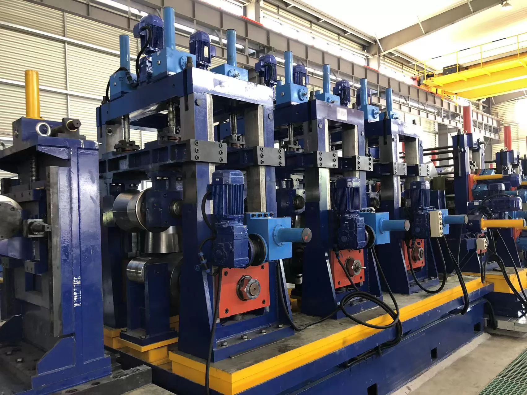
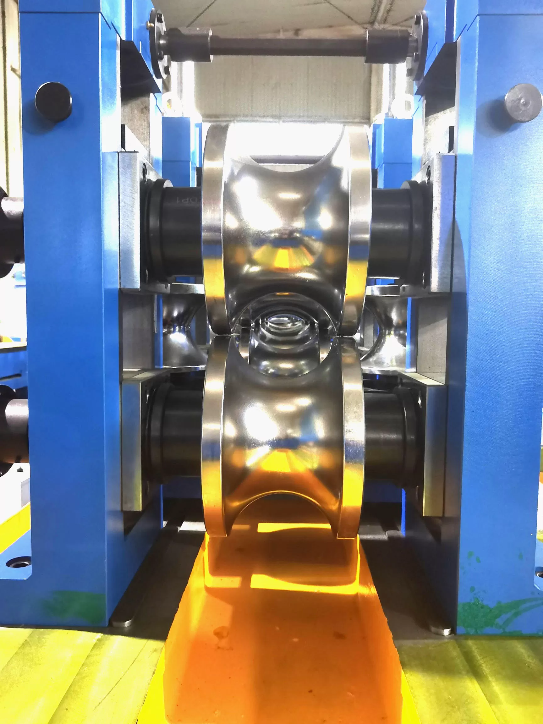
The forming bank sequentially shapes the flat strip into an open cylindrical
shell (an "open seam pipe"). This transformation must avoid thinning the center
gauge, stretching strip edges unevenly, or introducing residual longitudinal
stress.
Breakdown Section: Radial and W-Forming
In conventional breakdown roll passes, driven upper and lower rolls impose
progressive transverse bends. Modern high-capacity mills typically employ
W-forming tooling or cage forming systems. Cage forming uses clusters of
adjustable, non-driven vertical side rolls that bend the strip edges up early in
the sequence. This approach reduces tooling changes across multiple outer
diameters (ODs) and prevents the "edge stretching" that causes edge-wave defects
in high-yield-strength alloys.
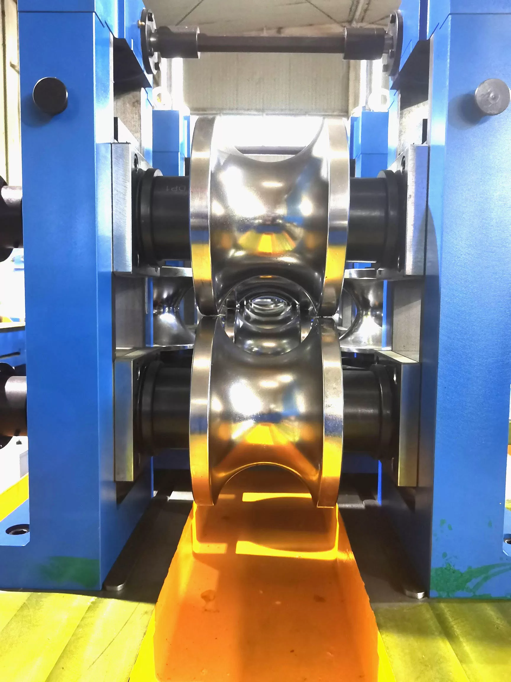
Fin Pass Section: Edge Presentation and Coining
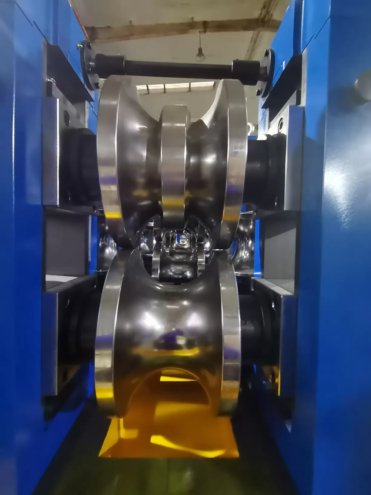
The final 2 to 4 forming stands are fin passes. Roll sets feature a central
circumferential fin (blade) that physically locates between the open strip
edges. These passes perform critical functions:
Edge Coining: The fin blades accurately set the profile
angle of the strip edges so they enter the weld zone parallel rather than
beveled.
Seam Orientation: The fin holds the open seam strictly on
top-dead-center (TDC), neutralizing any strip camber or rolling twist.
Girth Calibration: These passes control the outer
circumference precisely to govern the cross-sectional reduction delivered to the
squeeze rolls.
Phase 3: High-Frequency Electric Resistance Welding (ERW/HFW)
At the center of high-frequency mill tube manufacturing is
the joining phase, typically executed via High-Frequency Induction (HFI) or
High-Frequency Contact (HFC) welding running at frequencies from 200 to 500
kHz.
Skin Effect and Proximity Effect
High-frequency current does not behave like direct current. It operates under
two electromagnetic principles:
Skin Effect: Current flows primarily along the outermost
peripheral layer of the steel strip edges, concentrating thermal input to a
depth of only fractions of a millimeter.
Proximity Effect: Because the two strip edges converge
toward an apex, the current returns through the opposing edge, concentrating the
magnetic flux and focusing thermal energy precisely on the opposing edge
surfaces.
The V-Angle and Apex Dynamics
The convergent edges form an electrical "Vee." Stable welding requires
maintaining a V-angle between 3° and 7°. If the apex drifts too close to the
squeeze roll center line, edge overheating and pre-arcing cause cast brittle
zones. If the apex drifts too far upstream, thermal dissipation drops the
interface temperature below forging threshold, creating cold weld defects (lack
of fusion).
To maximize electrical efficiency, a water-cooled impeder (constructed from high-permeability manganese-zinc ferrite cores) is mounted
inside the open tube beneath the weld point. The impeder increases the magnetic
inductive reactance of the tube's interior path, preventing current from looping
wasted around the internal circumference and forcing it directly along the
converging V-edges.
Upset Forging and Scarfing
Once the strip edges reach a plastic forging state (1350°C–1450°C for
structural carbon steels), squeeze rolls force them together under high
mechanical pressure. Solid oxides, liquid melt layers, and slag inclusions are
expelled from the joint, creating internal and external weld beads (flash). A
continuous OD scarfer trims the hot outer flash flush with the base tube
profile, while an ID scarfing mandrel, supported internally, cuts the inside
weld bead to meet API, ASTM, or automotive hydraulic specifications.
Phase 4: In-Line Heat Treatment, Sizing, and Profile Modification
Because the rapid thermal rise and ambient quench of the HFW process creates
an as-welded martensitic or coarse bainitic microstructure along the narrow
Heat-Affected Zone (HAZ), targeted post-weld conditioning is mandatory for
critical structural applications.
Seam Normalization
Mid-frequency (1–3 kHz) induction heating heads track the weld seam inline
immediately after water quenching and scarfing. The equipment reheats the HAZ to
austenitizing temperatures (880°C–950°C), dissolving the hard, brittle phases
and allowing the seam to cool naturally into a ductile, uniform, fine-grained
ferrite-pearlite matrix that matches the parent metal's mechanical
properties.
Sizing and Turk’s Head Shaping
Once cooled in a regulated water-spray trough, the round tube enters the
sizing section to overcome residual ovality and roll-induced distortion:
Diameter Calibration: Driven sizing passes reduce the outer
diameter by 1% to 3%, working the material past its yield point to guarantee
consistent cross-sectional circularity and wall thickness tolerances.
Shape Conversion: To manufacture square, rectangular, or
complex polygonal hollow sections, the cylindrical hollow is driven through
progressive profile rolls or 4-roll universal stands (Turk’s Heads). Corner
radii are formed here under high compression without compromising the integrity
of the weld line.
Straightening: Turk’s head units, adjustable on horizontal
and vertical axes, neutralize mill-induced camber, sweep, and torsional
twist.
Phase 5: High-Precision Cutoff and Non-Destructive Testing (NDT)
The final processing stage balances mechanical speed with continuous
non-destructive inspection to prevent out-of-spec lengths from entering
downstream inventory.
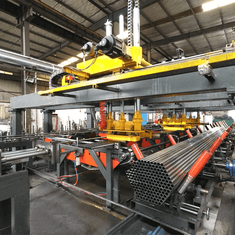
Inline Non-Destructive Testing: High-throughput lines
integrate rotary eddy-current arrays or phased-array ultrasonic testing (UT)
heads immediately after sizing. These systems detect internal weld laminations,
pinholes, unbonded cold welds, and wall under-gauge conditions in real time,
triggering spray-mark rejection flags.
Flying Cutoff Systems: Flying cold saws equipped with
tungsten-carbide-tipped (TCT) blades or high-speed HSS circular blades
synchronize dynamically with the line via servo-rack tracking. Cold sawing
eliminates the heavy thermal burrs, localized edge hardening, and end-squaring
defects typical of older friction abrasive wheels.
Crucial Engineering Variables in Modern Mill Tube Lines
Maintaining high overall equipment effectiveness (OEE) on a mill
tube line requires precise management of mechanical and tooling
variables:
Roll Tooling Wear Patterns: Abrasive wear on upper fin pass
blades and sizing shoulder profiles alters effective diameter metrics, shifting
edge strain patterns and leading to edge hooking or out-of-tolerance radii.
Tooling specialists at SANSO use high-vanadium tool steels
(e.g., D2, high-alloy powder metallurgy grades) and cryogenic treatments to
improve roll wear life.
Strip Width Tolerancing: Slitting tolerances directly
influence weld forge pressure. A mere +0.5 mm error across a wide slitting strip
overfills the fin passes, creates heavy squeeze upset, and wears roll bearings
prematurely. Under-width strip starves the squeeze rolls, leading to low forge
pressure and catastrophic weld defects.
Downtime Mitigation via Quick-Change Cassettes: Leading
tube operations use rafted or cassette-type mill stands. The entire set of
breakdown, fin, and sizing stands can be decoupled mechanically and lifted out
by crane, allowing changeovers to alternative profiles in under 45 minutes
instead of whole 8-hour operating shifts.
Frequently Asked Questions
What differentiates an ERW mill tube from a seamless tube?
An ERW (Electric Resistance Welded) mill tube is manufactured continuously
from cold-rolled or hot-rolled steel strip, formed into a cylinder, and welded
along its longitudinal seam using electric resistance or induction heat. A
seamless tube is produced by hot-piercing a solid cylindrical steel billet over
an internal mandrel, resulting in a hollow shell without a longitudinal weld
interface. ERW tubes deliver tighter wall-thickness tolerances, superior surface
finishes, and better concentricity, whereas seamless tubes eliminate the
heat-affected zone entirely for high-pressure applications.
Why does hook cracking occur along the weld seam of a mill tube?
Hook cracking typically stems from non-metallic inclusions (such as manganese
sulfides or silicates) present within the raw steel strip. During cold roll
forming and the subsequent squeeze roll upset phase, these inclusions are
redirected parallel to the tube's cross-sectional contour, curving toward the
inner or outer surface. Under hoop stress or mechanical expansion tests, these
redirected inclusions open up into hairline fissures resembling hooks.
How does an impeder improve the welding performance of a tube mill?
The impeder consists of a core of high-grade ferrite materials housed in a
non-metallic, heat-resistant casing through which coolant continuously flows.
When placed inside the open seam pipe directly below the induction coil, the
impeder channels the magnetic flux, dramatically raising the electrical
impedance of the current path around the inside wall of the tube. This forces
the high-frequency current to prioritize the low-resistance path along the
converging strip edges, increasing electrical efficiency and reducing required
generator power.
What standards govern testing for structural mill tube integrity?
Major international specifications include ASTM A500 (cold-formed welded and
seamless carbon steel structural tubing in rounds and shapes), ASTM A53 (pipe,
steel, black and hot-dipped, zinc-coated, welded and seamless), and EN 10219
(cold-formed welded structural hollow sections of non-alloy and fine grain
steels). Testing mandates typically specify reverse flattening, tensile
strength, yield strength, charpy V-notch impact toughness, and continuous inline
eddy-current or hydrostatic leak testing.
Can high-frequency tube mills produce non-round profiles directly?
Yes. Mills can run direct-forming tooling that shapes the strip into a square
or rectangular cross section prior to welding. However, the more common and
operationally stable method is the "round-to-shape" process. The strip is formed
and welded as a standard round tube—maximizing apex welding stability and
symmetry—and subsequently converted into square, rectangular, or elliptical
profiles within the cold sizing and Turk’s Head stands.
Upgrade Your Tube Milling Infrastructure with SANSO
High-yield, dimensionally accurate mill tube manufacturing
requires coordinated engineering across every mechanical stage: precise strip
accumulator mechanics, high-rigidity roll stands, low-loss impeder arrangements,
and dynamic flying cutoffs. Line deflection, bearing clearance errors, or
improper roll tooling profiles can quickly compound into surface marking, wall
thinning, and weld defects.
SANSO engineers complete, high-performance tube mill
processing systems, precision roll tooling, and cassette-based rapid changeover
architectures engineered to tight dimensional tolerances. Whether you are
expanding lines for ASTM structural sections, complex automotive profiles, or
high-volume mechanical tubing, our engineering team provides the machinery, roll
pass profiles, and field commissioning support to maximize your OEE and reduce
scrap rates.
Contact the engineering team at SANSO today to review your
project specifications, request tooling simulations, or receive a formal
machinery quote tailored to your production demands.