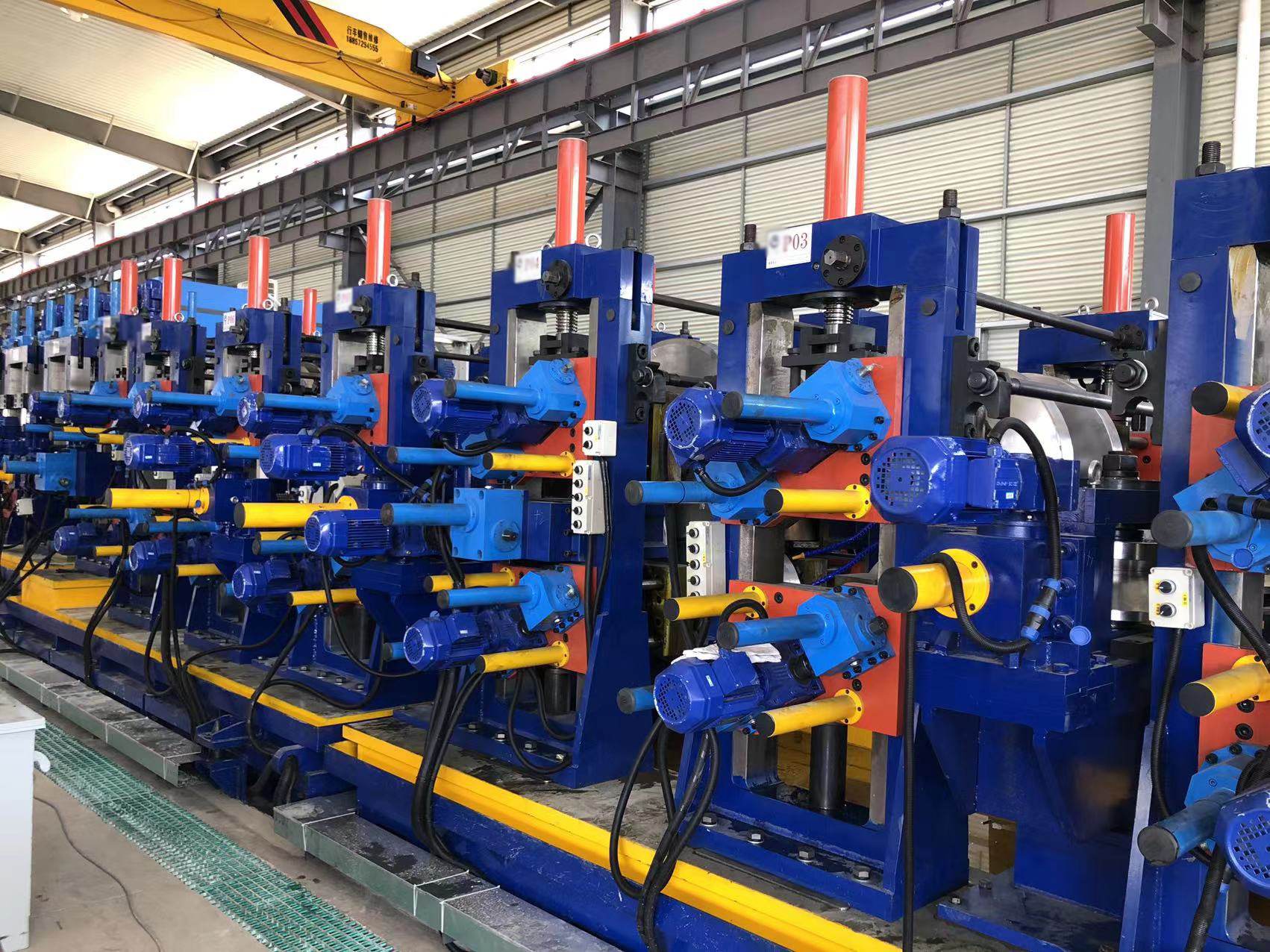
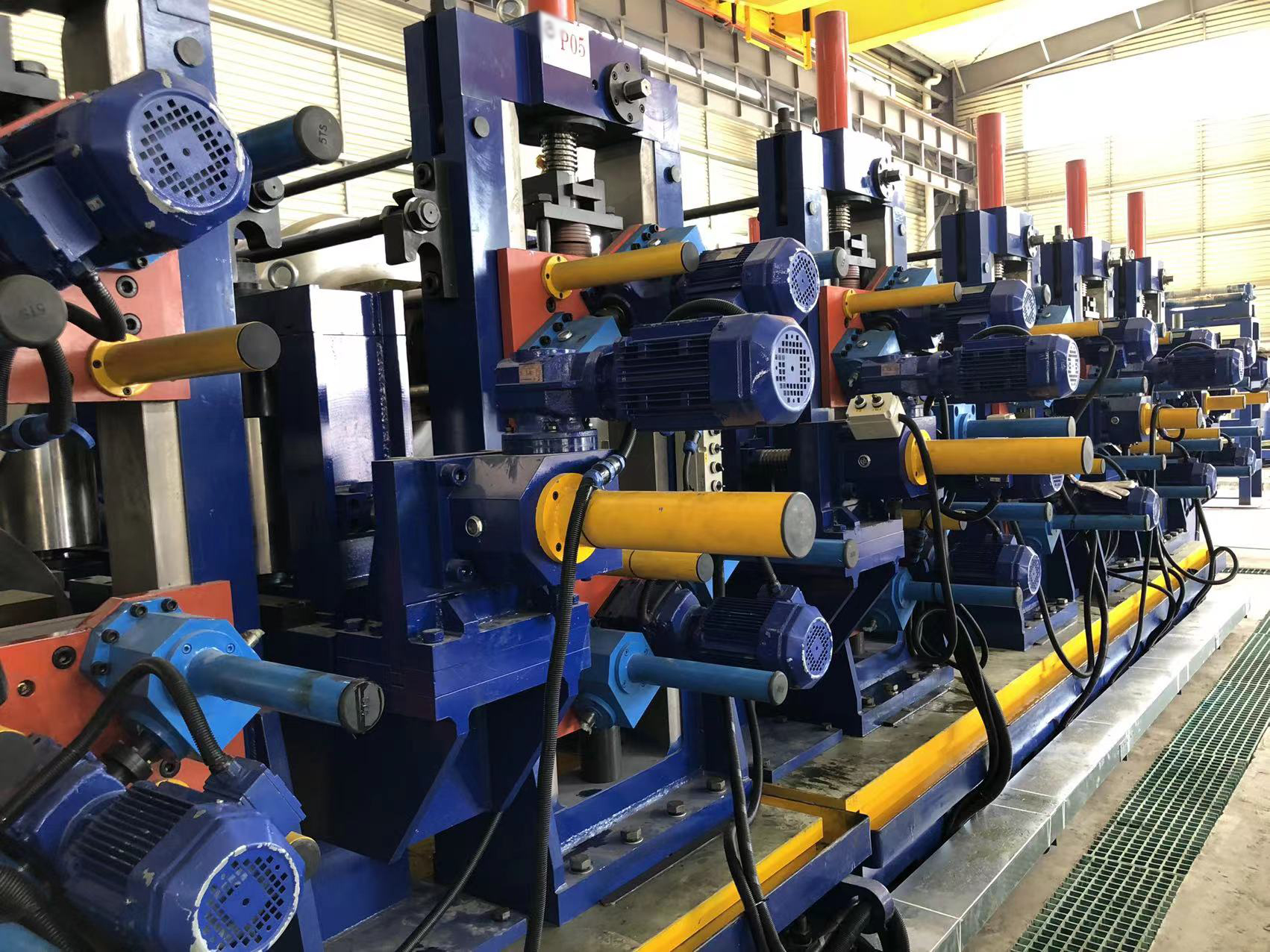
High-frequency induction welding (HFIW) stands as the industry standard for producing high-quality electric resistance welded (ERW) steel tubes. This process relies on generating intense heat at the joint edges of a formed steel strip before mechanically forging them together under high pressure. While the induction coil and the squeeze rolls are highly visible components of this process, the efficiency of the entire operation often depends on a quieter, internally positioned tool: the impeder in tube mill systems.
Without this key component, a significant portion of the electrical energy supplied to the induction coil would disperse throughout the interior of the tube, resulting in low welding speeds, high energy waste, and inconsistent weld quality. For manufacturers aiming to maintain high-speed production while preserving weld integrity, understanding the electromagnetics, mechanical placement, and maintenance of this tooling is paramount. Companies like SANSO design and manufacture high-precision forming and welding machinery designed to integrate these systems seamlessly, ensuring optimal energy transfer and robust seam quality.
To understand why an impeder is required, one must first analyze the behavior of high-frequency electrical currents. When a high-frequency current (typically ranging from 150 kHz to 400 kHz) is introduced into a copper induction coil surrounding the formed tube, it induces a secondary current within the metallic strip. This induced current must complete a closed loop. The goal of the welding process is to force this current to flow along the open edges of the strip, meeting at the apex (the exact point where the squeeze rolls forge the metal together).
However, high-frequency currents are governed by two distinct electromagnetic phenomena:
The Skin Effect: High-frequency current does not distribute evenly throughout a conductor. Instead, it concentrates near the outer boundaries or the "skin" of the material. The depth of this penetration decreases as the frequency increases, which helps concentrate heat on the immediate surfaces of the strip edges.
The Proximity Effect: When two conductors carrying current in opposite directions are placed near each other, the current concentrates on the surfaces closest to one another. In a tube mill, this forces the current to flow along the opposing edges of the weld vee, maximizing heating efficiency at the joint.
Despite these effects, the current naturally seeks the path of least electrical impedance. The inner surface of the formed tube body offers a massive alternative path. Without a barrier, the current will flow around the inside diameter of the tube instead of concentrating at the weld vee. This bypass path wastes energy, overheats the entire tube body, and prevents the strip edges from reaching the correct welding temperature.
The impeder in tube mill serves a simple yet vital role: it drastically increases the electrical impedance of the inner path of the tube. By placing a highly magnetic material inside the tube, directly underneath the induction coil, the inductive reactance of the internal current path rises to extreme levels. Because high-frequency current naturally avoids paths of high impedance, it is forced away from the tube interior and diverted directly to the strip edges forming the weld vee.
This redirection of current achieves several key operational benefits:
Concentrated Heating: Energy is focused precisely on the strip edges, heating them to the forging temperature (approximately 1300°C to 1400°C for carbon steel) within milliseconds.
Power Efficiency: Because the bypass current is minimized, the power required from the high-frequency welder is significantly reduced, resulting in immediate energy conservation.
Increased Line Speed: With more efficient heat concentration, the tube mill can operate at higher line speeds without sacrificing weld depth or seam quality.
An impeder assembly is composed of three primary structural elements: the ferrite core, the protective outer casing, and the internal cooling channels.
The ferrite core is the functional heart of the device. It is typically manufactured from manganese-zinc (MnZn) ferrite, a material chosen for its exceptionally high magnetic permeability and low electrical conductivity. This combination allows it to influence the magnetic field without conducting currents itself, which would otherwise cause internal heating. However, ferrite is inherently brittle and highly sensitive to temperature fluctuations.
The casing shields the fragile ferrite core from the harsh environment inside the tube mill, where it is exposed to flying weld spatter, mechanical vibrations, and intense radiant heat from the weld zone. These casings are constructed from highly durable, non-conductive, and heat-resistant materials, such as epoxy-glass laminates or silicone-glass compounds.
The cooling system is necessary because ferrite lose their magnetic properties if they exceed their Curie temperature (typically between 200°C and 250°C). If the core reaches this temperature, it becomes paramagnetic, and its ability to redirect current drops to near zero. Therefore, a continuous, high-volume flow of clean cooling water is mandatory to maintain the ferrite core well below its thermal limit during operation.
Choosing the correct configuration of an impeder in tube mill depends on the specific product specifications, tube diameters, and cleanliness requirements of the final product. There are two primary structural styles utilized in industrial manufacturing:
In a flow-through configuration, cooling water enters the rear of the impeder casing, flows directly over the surface of the ferrite cores, and discharges from the front of the casing directly into the interior of the welded tube. This style is highly popular because of its simplicity and high cooling volume. It is highly effective for larger diameter pipes where the presence of internal water does not interfere with subsequent manufacturing steps or where an inline drying system is active downstream.
For applications where the interior of the tube must remain dry—such as in small-diameter tubing, structural profiles, or when producing carbon steel tubes prone to internal rust—a return-flow impeder is utilized. This design features a closed cooling circuit. Water travels through a dedicated central channel, cools the ferrite, and is pulled back through a return manifold to be discharged outside the tube. While more complex to manufacture and maintain, return-flow models prevent water accumulation inside the welded pipe, protecting the product from internal corrosion.
Ferrite cores can be solid cylindrical blocks or serrated (fluted) profiles. Serrated cores feature longitudinal grooves running along their outer surface. These grooves serve two purposes: they increase the surface area exposed to the cooling water, enabling more efficient heat dissipation, and they provide dedicated channels for water flow, reducing the risk of air pockets that can cause localized overheating and thermal cracking.
To maximize the lifespan of an impeder in tube mill, operators must focus on precise positioning, water quality, and physical alignment within the weld section.
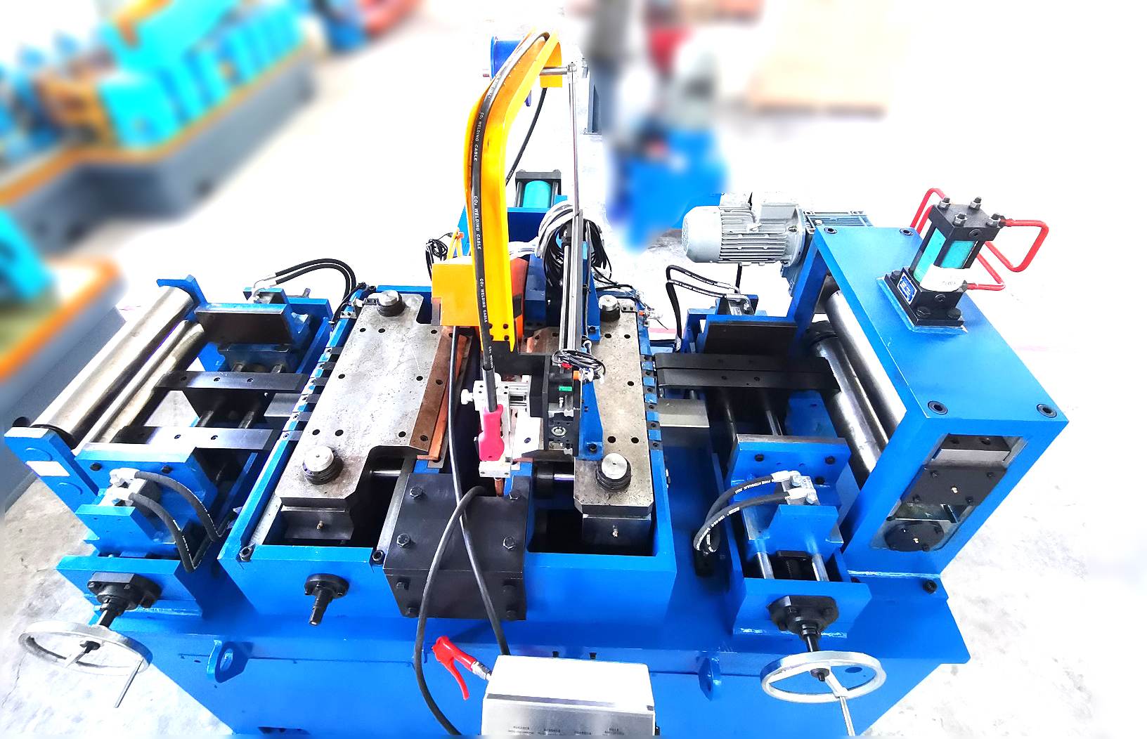
The physical position of the impeder relative to the induction coil and the weld rolls is a decisive factor in welding efficiency. The forward end of the ferrite core should ideally extend past the centerline of the squeeze rolls by approximately 1.5 to 3 millimeters. If the impeder is positioned too far upstream (away from the weld rolls), the current path lengthens, reducing energy concentration at the apex. Conversely, if it is placed too far downstream, the intense heat and mechanical pressure of the squeeze rolls will cause premature casing wear and thermal destruction of the ferrite.
Additionally, the impeder must be aligned perfectly parallel to the tube axis. Any sagging or misalignment can cause the casing to rub against the moving inner wall of the tube, resulting in rapid abrasive wear and mechanical failure.
| Parameter | Target Setting / Condition | Operational Impact of Deviation |
|---|---|---|
| Forward Position | 1.5 to 3 mm past squeeze roll centerline | Too far back causes poor weld heating; too far forward causes thermal destruction. |
| Water Flow Rate | Min. 15 to 30 liters/minute (depending on size) | Insufficient flow leads to ferrite reaching Curie temperature and losing efficiency. |
| Water Pressure | 3 to 5 bar | Low pressure allows steam pockets to form; excessive pressure can rupture casings. |
| Water Filtration | Filtered down to 50 microns (magnetic filtration) | Iron fines accumulate on magnetic ferrite, clogging flow and causing thermal stress. |
| Fill Factor | 60% to 80% of tube inner diameter | Too small reduces electrical efficiency; too large blocks cooling and weld bead clearance. |
Because the ferrite core is highly magnetic, any iron particles, mill scale, or magnetic debris suspended in the cooling water will be drawn directly to the core surface. Over time, these particles accumulate, clogging the narrow water passages inside the casing. This accumulation leads to localized hot spots, thermal shocking, and catastrophic cracking of the ferrite.
To prevent this, the cooling water circuit must be equipped with high-efficiency magnetic separators and fine-mesh mechanical filters. Closed-loop cooling systems utilizing demineralized water or water treated with rust inhibitors are highly recommended to prevent calcium scale buildup, which acts as a thermal insulator and reduces cooling performance.
In high-volume tube manufacturing, maintaining consistent weld quality requires addressing several common operational challenges. For instance, when a tube mill is running at high speeds, mechanical vibrations can cause the internal support mandrel of the impeder to whip or sag. When this occurs, the distance between the ferrite and the tube wall fluctuates, causing variations in electrical impedance and resulting in "cold welds" or weld seam dropouts.
To mitigate this issue, manufacturers like SANSO recommend implementing rigid, heavy-duty mandrel support assemblies that are adjustable in three axes. These specialized supports allow operators to fine-tune the positioning of the internal tooling without stopping the mill, ensuring that the impeder remains perfectly centered even under high mechanical loads.
Another common issue is the accumulation of internal weld spatter. As the squeeze rolls join the edges, excess molten metal is squeezed inward, creating an internal weld bead (or flash). This hot, sharp metal can scrape against the outer casing of the impeder. Utilizing high-performance, wear-resistant casing materials and ensuring a sufficient gap between the top of the casing and the weld seam helps prolong the life of the assembly.
By integrating a high-performance impeder in tube mill into your production setup, you establish a foundation for highly efficient, stable, and repeatable high-frequency welding. However, this component does not work in isolation. It must be paired with precise roll forming passes, robust squeeze roll stands, and stable high-frequency power delivery systems.
When all these variables are aligned, tube manufacturers experience less scrap, reduced power consumption, and highly uniform weld microstructures that can easily withstand downstream processing, such as bending, flaring, and hydroforming. Investing in high-grade ferrite cores and robust cooling auxiliary equipment is a direct path to optimizing the yield of your tube mill line.
Q1: How often should the ferrite cores in a tube mill impeder be replaced?
A1: The lifespan of a ferrite core depends heavily on cooling efficiency and physical protection. In a properly cooled, clean environment with adequate filtration, a core can last for several weeks of continuous operation. However, if cooling water flow is interrupted, or if magnetic particles clog the casing, the ferrite can crack from thermal shock within minutes, requiring immediate replacement.
Q2: Can I run a tube mill without an impeder?
A2: While it is physically possible to run the mill without one, the process becomes extremely inefficient. Without the increased impedance provided by the ferrite core, much of the high-frequency current flows around the inside of the tube. This would require massive increases in welder power output, drastically slow down maximum welding speeds, and likely result in incomplete fusion and cold weld defects.
Q3: What is the optimal water pressure for cooling an impeder assembly?
A3: The recommended water pressure is typically between 3 and 5 bar. If the pressure is too low, steam pockets can form on the surface of the hot ferrite, leading to localized overheating and cracking. If the pressure is too high, it may cause mechanical damage to the non-metallic casing or lead to seal failures at the connection joints.
Q4: Why is a return-flow impeder preferred over a flow-through model for certain tube materials?
A4: Return-flow models are selected when the interior of the tube must remain clean and completely dry. For example, high-strength steels or tubes intended for immediate internal coating, galvanizing, or painting cannot tolerate standing water inside the tube. The return-flow system routes all cooling water back out of the entry side, preventing internal rust and contamination.
Q5: How does the "fill factor" affect the efficiency of high-frequency welding?
A5: The fill factor is the ratio of the impeder's outer diameter to the internal diameter of the tube being welded. A higher fill factor (typically 60% to 80%) places the magnetic ferrite closer to the tube wall, which maximizes electrical impedance and increases energy efficiency. However, sufficient clearance must always be maintained to allow for cooling water flow and to prevent contact with the internal weld bead.
Achieving consistent weld quality and high operational efficiency requires deep engineering expertise and precision-engineered machinery. The correct selection, alignment, and cooling of your internal tooling are vital steps toward reducing energy waste and securing flawless weld seams. Our engineering team specializes in configuring robust, high-performance forming systems tailored to your specific production demands.
To discuss your tube mill configuration, optimize your tooling setup, or request a detailed quotation for high-precision manufacturing equipment, please contact our technical sales department today. Let us help you find the precise mechanical solution to enhance your line throughput and product quality.