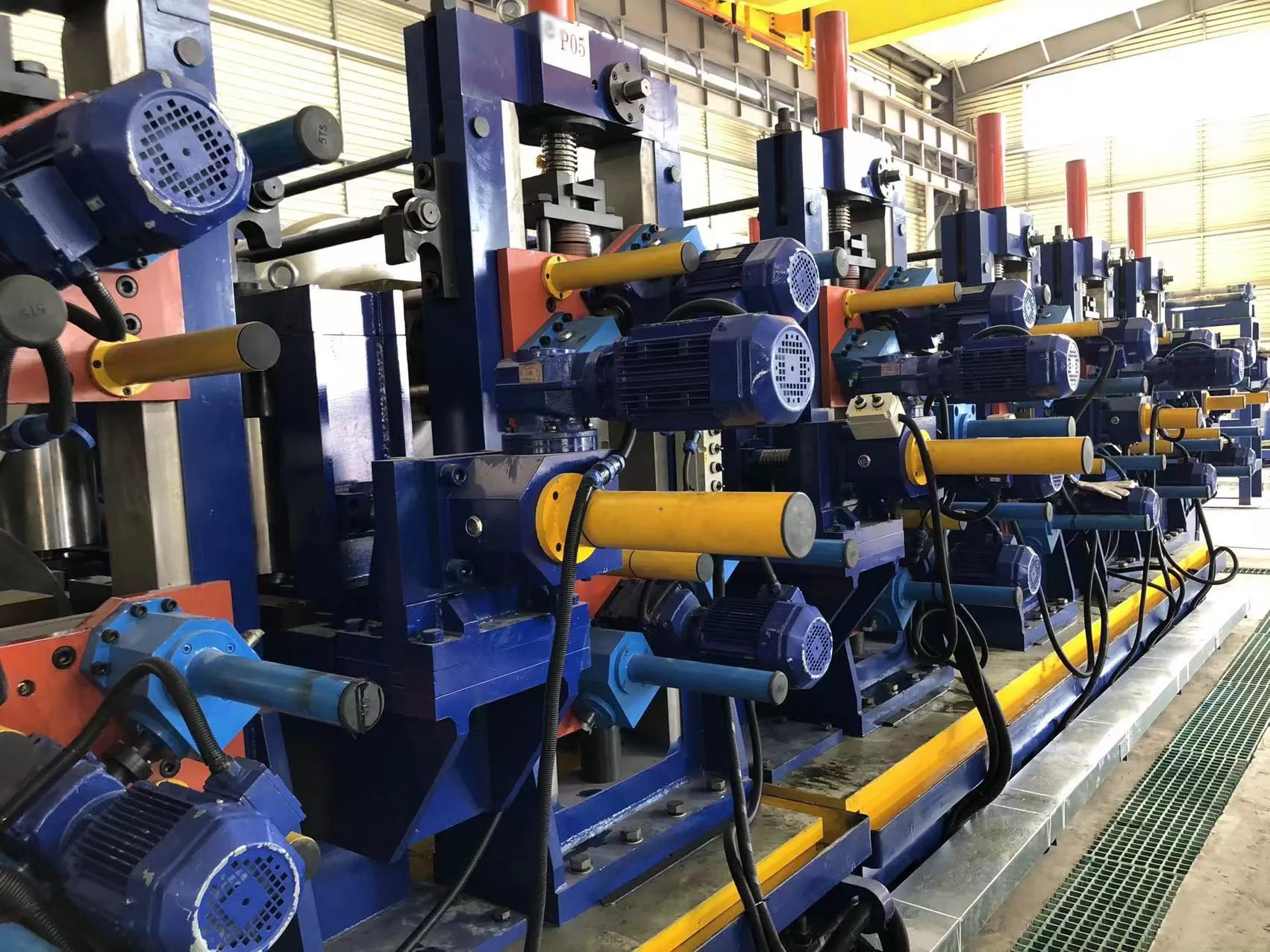
High-frequency welded pipe production and continuous roll forming rely on
controlled material pay-off at the entry section. High-tensile steel coils
present significant physical mass and mechanical springback during uncoiling.
Improper strip unwinding leads to material slippage, surface abrasion, line
misalignment, and unplanned downtime. Selecting appropriate entry equipment
ensures that strip feeding matches downstream processing speeds while protecting
structural machinery from fatigue failure.
The continuous supply of strip metal into the forming section begins at the
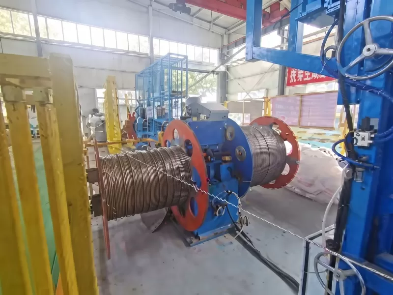
uncoiling station. A heavy-duty hydraulic uncoiler serves as the primary
load-bearing unit, securing the coil core internally while maintaining
calibrated back-tension during unwinding. Equipment manufactured by SANSO is
engineered to withstand severe dynamic load conditions generated by thick-wall
hot-rolled steel and high-yield alloy coils.

Mandrel Architecture and Hydraulic Expansion Mechanisms
The central shaft assembly handles both rotational torque and cantilever load
moments. Standard mechanical decoilers that rely on manual screw expansion often
struggle with internal slip when heavy braking or high line tension is applied.
Hydraulic expansion solves this by using continuous fluid force to drive
internal wedge mechanisms, forcing expansion segments firmly against the inner
diameter of the coil.
Unlike manual mechanical decoilers, a heavy-duty hydraulic uncoiler applies
uniform radial forces across the bore through dedicated fluid actuators. The
internal expansion structure usually employs a four-segment wedge slider
arrangement or a heavy-duty linkage configuration. A double-acting hydraulic
cylinder mounted at the rear of the main spindle actuates a central pull-rod.
This rod pulls sliding wedges horizontally, converting linear cylinder force
into radial outward thrust across the expansion leaves.
Inner Diameter Accommodation: Standard heavy-gauge coils
come with internal bore sizes of 508 mm (20 inches) or 610 mm (24 inches).
Specialized heavy-duty mandrels use removable extension shoes or extended
hydraulic stroke capabilities to clamp bore diameters up to 760 mm without
compromising concentricity.
Uniform Clamping Pressure: Regulated hydraulic fluid
distribution ensures equal outward pressure across the entire width of the inner
wrap. This eliminates high localized stresses that deform thin-wall coils while
providing sufficient clamping friction to prevent inner-wrap slip when unwinding
12 mm thick high-yield steel strip.
Cantilever Load Distribution: The main spindle endures
severe bending stress when supporting coil weights up to 30 metric tons.
High-tensile alloy steel forgings, such as 42CrMo, undergo heat treatment,
stress relief, and precision grinding to handle dynamic load shifts. The spindle
rotates within dual spherical roller bearings housed in high-strength cast steel
pedestals, absorbing both radial loads and axial thrust.
Strip Tension Control and Auxiliary Handling Units
Line payout speed must respond smoothly to the demands of downstream
processing, such as accumulator filling or direct mill intake. When the line
stops unexpectedly, high rotational inertia can cause coil over-travel,
generating loose wraps and surface scratching.
Integrating active mechanical and hydraulic auxiliary devices onto the main
frame maintains tight wrap geometry throughout the entire uncoiling cycle.
Hold-Down and Snubber Arm Assemblies
Cutting outer steel packaging straps on high-yield steel coils can release
severe springback energy. A heavy-duty top hold-down arm, powered by a
dual-acting hydraulic cylinder, presses a wide polyurethane roll against the
outer wrap. The high-friction roller restrains outer coil layers during strap
removal and guides the leading edge smoothly into the peeler blade throat
without operator intervention.
Proportional Back-Tension Braking
Continuous web tension between the pay-off station and the entry leveler is
required to avoid strip sagging and tracking drift. Caliper disc brakes
installed on the rear of the main shaft provide dynamic torque control. As the
coil diameter decreases during processing, proportional hydraulic or pneumatic
control valves gradually lower brake torque to keep web tension consistent from
full coil to core.
Automated Coil Loading Integration
Manual alignment of multi-ton coils using overhead cranes increases
changeover time and creates mechanical shock hazards. To reduce cycle time
between coil changes, a hydraulic uncoiler works in conjunction with a motorized
coil loading car. The car features a hydraulic V-nest lift mechanism that raises
the coil to exact spindle center elevation. Drive motors then traverse the car
horizontally, sliding the coil directly onto the expanded mandrel. Integrated
strip processing lines from SANSO leverage synchronized coil car hydraulics to
complete coil changeover in under three minutes.
Structural Tracking and Base Alignment Mechanics
Angular or linear misalignment between the unwinding strip and the mill entry
centerline introduces edge wave defects, side wear on forming rollers, and
irregular weld seam alignment. Modern heavy-duty unwinding systems resolve line
drift through automated sub-base side-shifting.
The hydraulic uncoiler assembly mounts on precision-machined linear guideways
or heavy dovetail slides anchored to the floor foundation. Hydraulic cylinders
located within the lower frame move the main assembly laterally up to ±100 mm
relative to the floor foundation. Non-contact ultrasonic or optical edge
detection sensors mounted at the flattener entry register strip drift and
transmit proportional signals to the side-shift hydraulic control unit. The
system continuously adjusts the base position, keeping the strip center aligned
with the forming axis.
When handling heavy-gauge plate (thickness exceeding 10 mm), a hydraulic
peeler blade extends into the coil wedge to lift the leading edge, while a
hydraulic hold-down roll applies downward force to flatten end curvature before
the material reaches the pinch rolls.
Engineering Selection Parameters for Heavy-Duty Lines
Specifying processing equipment requires careful analysis of material
specifications, coil dimensions, and mechanical duty cycles.
Material Strength Specifications: Processing high-yield
structural steels requires increased mandrel expansion force, higher hold-down
arm cylinder capacity, and heavy-duty brake friction materials to manage
material resilience.
Coil Mass and Dimensional Ranges: Spindle diameter, bearing
span, and base plate thickness must be designed according to maximum coil weight
(e.g., 10t, 15t, 20t, 30t) and maximum strip width.
Line Speed and Acceleration: High-speed pipe lines
operating above 60 meters per minute require dynamically balanced spindle
assemblies and active oil-chilled brake systems to handle heat generation during
frequent start-stop cycles.
Hydraulic System Sizing: System pressure (typically
operating between 12 MPa and 18 MPa) and fluid flow rates must support
simultaneous execution of expansion, side-shifting, and snubber roll control
without pressure drops.
Hydraulic Fluid Maintenance and Component Reliability
Sustained industrial duty demands systematic maintenance of fluid power units
and mechanical wear interfaces. Contaminated hydraulic fluid accelerates valve
seat erosion and damages cylinder piston seals, leading to pressure loss in
internal expansion circuits.
Hydraulic oil filtration systems must maintain oil cleanliness to ISO 4406
standard 16/14/11. Regular oil analysis monitors moisture accumulation,
particulate buildup, and fluid viscosity loss. Lubrication protocols for
internal mandrel sliding surfaces require high-pressure molybdenum disulfide
grease to prevent galling on hardened alloy wear plates under high radial
expansion force. Daily visual checks of main spindle seals prevent fluid
contamination from reaching brake surfaces or support bearings.
Frequently Asked Questions
What is the primary operational difference between a single-mandrel and a
double-mandrel hydraulic uncoiler?
Single-mandrel units feature a single main spindle and cantilever frame,
making them suitable for wide, heavy steel coils where high structural rigidity
is required. Double-mandrel units feature two opposing spindle heads mounted on
a rotating base or sliding frame, allowing an operator to load a new coil on one
side while the other side feeds the operating mill line, minimizing line
changeover time.
How does hydraulic expansion prevent internal coil slippage during
braking?
Hydraulic expansion uses high-pressure cylinders to force internal sliding
wedges against heavy expansion leaves. This mechanical advantage generates high
radial forces across the coil bore, producing sufficient friction torque to
prevent internal coil wrap movement during rapid deceleration or high
back-tension conditions.
What mechanisms prevent cylinder pressure drop in a heavy-duty hydraulic
uncoiler setup during power interruptions?
Expansion circuits incorporate pilot-operated check valves or hydraulic
accumulators mounted directly onto the cylinder manifold. These safety valves
lock fluid inside the cylinder chamber if main hydraulic pressure drops,
maintaining positive clamping force on the coil bore until system power is
restored.
Why is automatic side-shifting important for high-frequency welded pipe
production?
Automatic side-shifting compensates for camber and telescoping within master
coils. By keeping the strip precisely centered as it enters the forming rolls,
side-shifting prevents uneven edge deformation, reduces edge trim waste, and
ensures consistent strip alignment at the high-frequency welding point.
How often should mandrel sliding wear plates be lubricated?
In high-tonnage production settings, mandrel sliding wedges and wear plates
should be lubricated every 40 to 50 operating hours using heavy-duty
high-pressure grease containing molybdenum disulfide. Regular lubrication
reduces friction, prevents surface galling, and ensures uniform expansion force
across all segments.
Engineering Proposals and Inquiry Guidance
Selecting precise coil handling machinery requires aligning equipment
structural ratings with your specific material yield strength, coil weight
limits, and mill entry speeds. SANSO designs heavy-duty uncoiling and strip
preparation machinery customized to exact plant configurations and duty cycles.
For engineering evaluations, custom structural drawings, or detailed budgetary
proposals, send your line parameters and production requirements to info@sansohftubemill.com to consult directly with our
engineering specialist team.