In metal stamping, roll forming, and electric resistance welded (ERW) tube
production, uncoiling marks the initial mechanical contact point with raw steel
coil. The method chosen to hold, expand, and unwind coiled metal dictates
dimensional stability, surface protection, and downstream feeding accuracy.
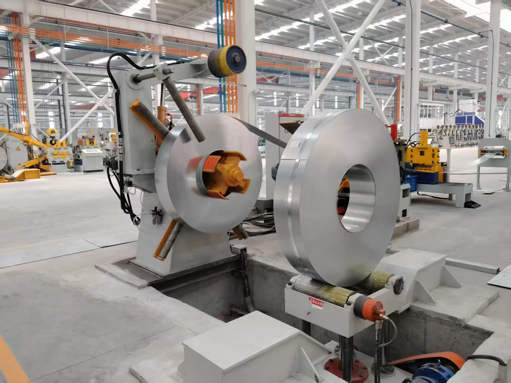
Among coil handling systems, the manual decoiler machine remains a foundational, highly cost-effective solution for short-run production,
specialized tube mills, and tight workshop footprints.
Unlike powered uncoiling units that use dedicated gearmotors and ultrasonic
loop sensors, a non-powered manual decoiler machine relies on
mechanical drag and downstream tensile force. Understanding the mechanical
mechanics, thermal limitations of friction braking, and mandrel alignment
protocols is critical for plant engineers aiming to eliminate defect patterns
such as strip telescoping, edge scoring, and variable back tension.
Decoupling Mechanics: Manual Decoiler Machine vs. Motorized Uncoiler
Systems
Selecting between non-powered and powered coil handling equipment requires
evaluating material mechanical properties, feed velocity, and shop floor space
constraints.
Kinematic Pull vs. Driven Rotation
A non-powered manual decoiler machine possesses no internal
driving motor. Rotational torque is generated externally by the downstream
equipment—such as a straightener, roll former, or feeder—pulling the metal
strip. To control rotational inertia and prevent strip overrun during rapid
decelerations, the decoiler utilizes an adjustable friction brake assembly. This
setup minimizes space requirements by eliminating the large material slack loop
necessary for motor-driven systems.
Conversely, a motorized uncoiler actively rotates the main spindle. Variable
speed AC drives or hydraulic motors respond to sensor arm inputs, continuously
maintaining a loose material loop. Motorized uncoiler lines are better suited
for extremely thin or highly sensitive substrates, as self-driven rotation
minimizes direct pull stress on the strip.
Material Limitations and Drag Friction Dynamics
Thick-Gauge & High-Yield Plate: Ideal for non-powered
manual decoilers. Stronger materials easily withstand the drag force required to
turn the heavy mandrel without suffering plastic elongation or cross-sectional
necking.
Thin-Gauge Materials (< 0.5 mm): Thin coil stock pulled
against a static friction brake risks edge distortion or yield stretching. In
these applications, motorized decoiling is preferable unless drag brake torque
is precisely controlled.
Surface Sensitivity: Polished stainless steel, aluminum, or
pre-painted metal can develop scratch marks under excessive pull tension if the
mandrel slip is unmanaged.
Anatomic Overview of Manual Decoiler Machine Components
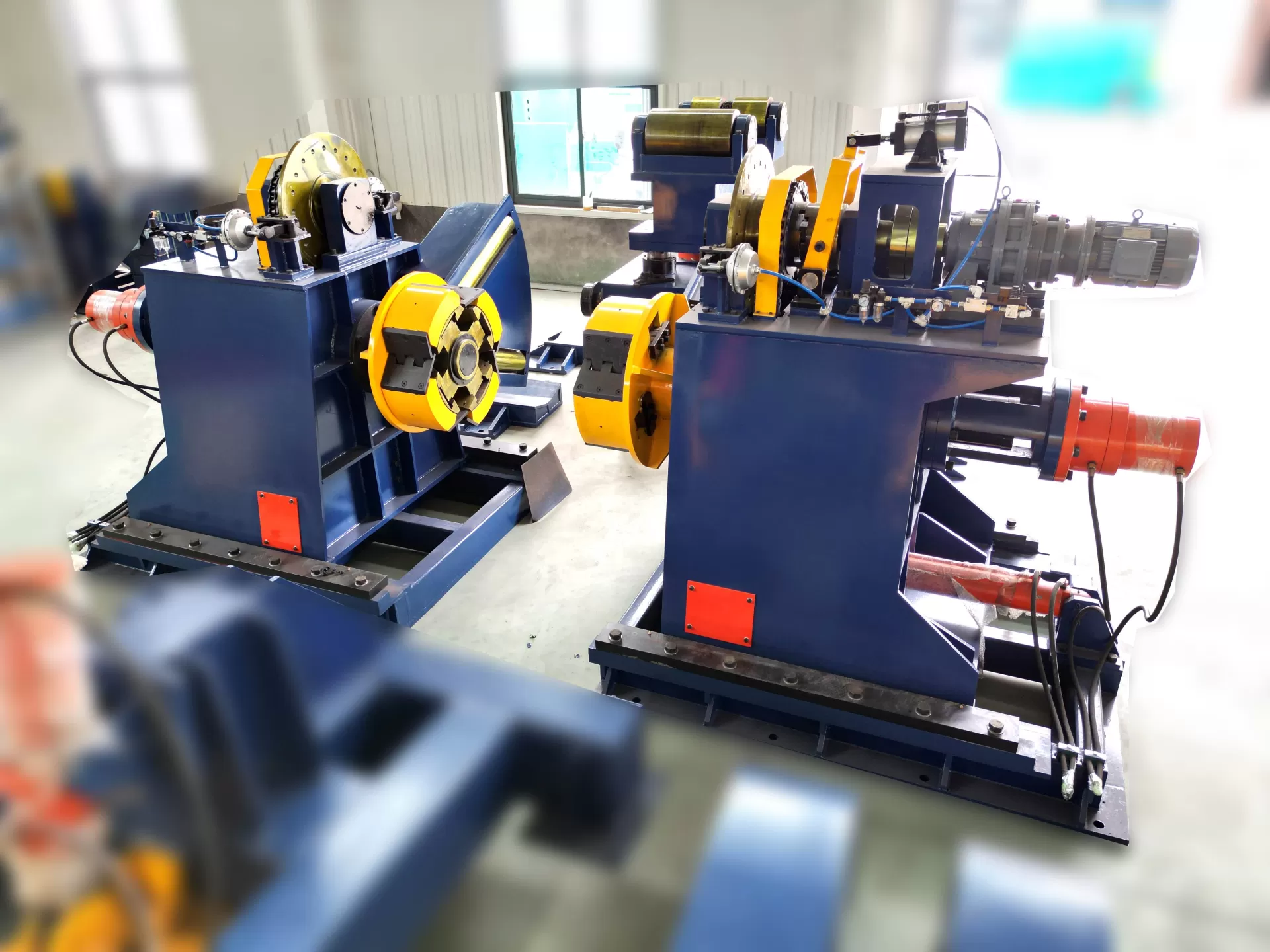
A heavy-duty manual decoiler machine engineered by
SANSO consists of five critical structural sub-assemblies
designed to absorb dynamic vibration and sustain cantilevered loads:
Structural Steel Base Frame: Fabricated from thick-walled
box sections or I-beams with pre-drilled anchor locations. Base mass (typically
300 kg to 800 kg) provides lower center-of-gravity stability to counter
overturning moments during high-speed feed cycles.
Segmented Expansion Mandrel: Machined from high-tensile
40Cr alloy steel with induction-hardened segment surfaces (HRC 45–50). Expansion
is actuated mechanically via a manual handwheel or heavy toggle lever driving an
internal wedge spindle. Standard expansion ranges cover 380 mm to 520 mm
internal diameter (ID) tolerances.
Adjustable Friction Brake Assembly: Utilizes heavy-duty
band brakes or caliper disc systems acting directly on the main shaft.
Mechanical friction adjustment allows operators to calibrate drag torque from 0
to 600 Nm to match coil weight and process velocity.
Hold-Down Roller Assembly: A spring-loaded or pneumatic arm
that applies downward force on the coil's outer diameter (OD). This prevents the
outer wraps from clock-springing during band cutting and initial threading.
Lateral Coil Centering Guides: Adjustable vertical side
plates or nylon-faced guide arms that fix the coil along its center line,
preventing lateral layer displacement.
Engineering Sizing and Selection Criteria
Specifying the correct manual decoiler machine requires
matching mechanical load capacity against operational slitting and roll-forming
parameters.
| Parameter | Standard Value Range | Engineering Selection Logic |
|---|
| Coil Weight Capacity | 500 kg – 2,000 kg | Calculated based on maximum coil load; ensures shaft deflection remains
under 0.05 mm/m. |
| Coil Inner Diameter (ID) | 380–450 mm / 450–520 mm | Mandrel collapsed diameter must be at least 15 mm smaller than coil ID for
loading clearance. |
| Coil Outer Diameter (OD) | 800 mm – 1,200 mm | Larger OD increases total rotational inertia, requiring higher brake drag
torque capability. |
| Strip Width Capability | 30 mm – 400 mm | Mandrel face length must equal or exceed maximum strip width plus side guide
clearance. |
| Maximum Uncoiling Speed | 20 m/min – 50 m/min | Upper limit for drag-brake heat dissipation without thermal fade. Higher
speeds require motorized equipment. |
Operational Troubleshooting: Correcting Uncoiling Defect Patterns
Field data collected across tube mill operations highlights five main
physical causes for line stoppages and product scrap during manual
uncoiling:
1. Coil Telescoping (Lateral Layer Slippage)
Cause: Misalignment between the mandrel axis and downstream
pinch rolls, or improper initial expansion torque leading to coil slippage on
the mandrel segments.
Solution: Verify mandrel-to-line squareness using precision
optical alignment or laser measures. Tighten the expansion handwheel to
specified mechanical torque (30–50 Nm). Engage adjustable side guide rollers
lined with low-friction UHMWPE to retain coil edges.
2. Edge Scalloping and Burr Formation
Cause: Metal strip dragging against metallic side flanges or
misaligned entry guides during pay-off.
Solution: Install nylon or composite edge guides with a 1.0
mm to 1.5 mm lateral play tolerance per side. Ensure mandrel expansion remains
concentric by inspecting radial runout with a dial indicator (acceptable runout
< 0.5 mm).
3. Inconsistent Back Tension and Strip Sag
Cause: Fixed mechanical brakes cannot dynamically adjust
drag torque as the coil OD decreases over time. Because torque required drops
directly with diminishing radius ($T = F \times r$), friction drag set for a
full coil becomes excessive on a near-empty hub.
Solution: Operators should manually adjust the brake
handwheel at scheduled intervals during long production runs. For tighter
process control, upgrade the friction assembly to a bolt-on pneumatic disc brake
modulated by a mechanical dancer roller.
4. Mandrel Wedge Seizure
Cause: Fine oxide scale, steel dust, or lack of lubrication
on internal sliding wedge surfaces.
Solution: Execute weekly cleaning cycles using solvent
degreasers, followed by high-pressure molybdenum disulfide grease applied to
sliding contact joints. Never strike expansion segments directly with steel
hammers.
5. Brake Liner Thermal Glazing
Cause: Continuous heavy friction generating interface
temperatures exceeding the thermal rating of standard brake linings, hardening
the friction material and losing stop force.
Solution: Inspect brake linings every 500 operating hours.
Replace glazed or oil-contaminated linings with non-asbestos woven friction
materials rated for elevated temperature stability.
Comparative Analysis: Manual, Hydraulic, and Motorized Uncoilers
Choosing the correct equipment platform requires balancing capital
expenditure against labor costs and setup speed.
| Operational Attribute | Manual Decoiler Machine | Hydraulic Uncoiler | Motorized Uncoiler |
|---|
| Payload Range | 500 – 2,000 kg | 2,000 – 10,000 kg | 5,000 – 30,000 kg |
| Mandrel Actuation | Manual Handwheel / Lever | Hydraulic Cylinder Expansion | Hydraulic or Electric Drive |
| Speed Capability | Up to 50 m/min | Up to 120 m/min | Up to 300 m/min |
| Maintenance Complexity | Very Low (Mechanical only) | Medium (Hydraulic pumps/valves) | High (Motors, VFDs, Sensors) |
| Capital Investment | Lowest (1x Baseline) | Moderate (4x–6x Baseline) | High (8x–12x Baseline) |
For operations running coil weights under 2,000 kg with modest speed demands,
a manual decoiler machine offers the fastest capital payoff,
minimal maintenance downtime, and zero electrical hookup constraints.
Maximizing Line Efficiency with SANSO Integrated Systems
A stand-alone non-powered decoiler achieves its highest operational utility
when matched with compatible coil processing accessories. SANSO manufactures engineered uncoiling stations designed for quick integration into
tube mills and roll-forming frames:
Integral Pinch-Levelers: Five-roller entry flatteners
positioned immediately downstream of the mandrel strip head to eliminate coil
set before entry into forming passes.
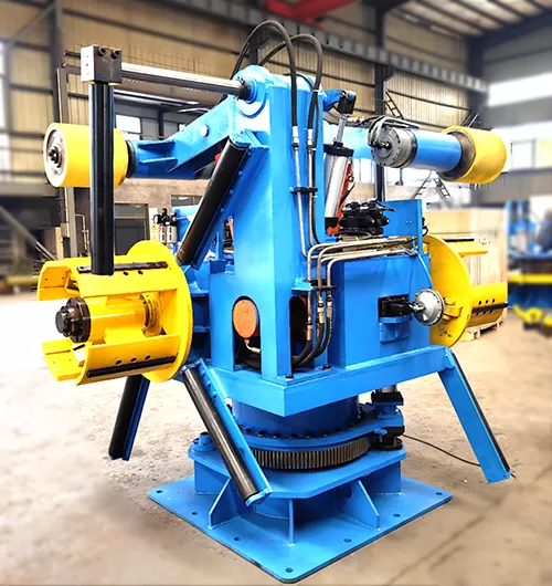
Hydraulic Loading Arms: Pivot arms mounted to manual bases
that lift 2-ton coils from floor level to mandrel center line, eliminating the
complete reliance on overhead cranes or forklifts during loading cycles.
Shear-Welding Stations: Compact end-shear and joining
tables that allow quick butt-welding of old coil tails to new strip heads,
minimizing line re-threading time.
Frequently Asked Questions
What is the safe load limit for a manual decoiler machine?
Standard manual decoiler designs comfortably handle payload weights up to
2,000 kg. Exceeding 2,000 kg increases the effort required for manual handwheel
expansion and risks elastic bending of the cantilevered main shaft. For loads
beyond 2,000 kg, power-assisted hydraulic expansion uncoilers are
recommended.
How is brake torque properly calibrated on a manual decoiler?
An initial baseline formula for setting brake drag torque is: Brake Torque
(Nm) = Coil Mass (kg) × 0.1. For example, a 1,000 kg coil typically requires an
initial setting around 100 Nm. Fine-tune this during lower-speed threading so
that the material strip maintains a slight taut profile without drooping to the
shop floor or lifting off downstream rollers.
Can a manual decoiler be upgraded to pneumatic tension control?
Yes. Non-powered manual decoilers can be retrofitted with a pneumatic disc
brake kit controlled by an inline proportional regulator and dancer arm
feedback. This modification automatically scales down brake pressure as the coil
outer diameter decreases during production.
What routine maintenance schedule is required for long mandrel service
life?
Clean and re-grease the internal expansion threads and sliding wedges weekly
with high-pressure molybdenum disulfide grease. Inspect brake pad thickness
every month; linings worn past 2.0 mm should be replaced immediately to avoid
damaging the iron brake drum surface.
How do operators avoid damaging sensitive strip materials on a manual
unit?
Use polyurethane-coated or rubber-sleeved mandrel segments to prevent
internal coil scratches. Ensure drag brake torque is kept at the minimum force
required to stop coasting, minimizing tensile friction on the unrolling material
layer.
Optimize Your Line Productivity with SANSO Engineering Solutions
Whether you are upgrading an existing tube mill line or setting up a modern
short-run roll forming operation, choosing robust, precisely aligned
coil-handling equipment is essential for maximizing uptime and material yield.
SANSO designs and manufactures heavy-duty, long-service
manual decoiler machine configurations tailored to your
specific strip width, inner diameter, and plant footprint requirements.
Ready to elevate your production efficiency? Contact the B2B
engineering team at SANSO today to receive detailed technical
datasheets, CAD line layouts, and competitive factory-direct quotations for your
next project.