The transition from manual coil unloading to a fully motorized
decoiler represents one of the most significant productivity
improvements in contemporary welded pipe manufacturing. For production managers
and plant engineers, the decoiler is not merely a stand-alone unit; it is the
critical entry point that determines the entire downstream process stability. A
poorly selected or incorrectly operated unit introduces variables that cascade
into welding inconsistencies, dimensional drift, and unplanned downtime. This
analysis examines the engineering principles, operational parameters, and
integration strategies that define high-performance coil feeding systems, with
particular attention to the demands of continuous high-speed tube mills.
Coil processing begins with the uncoiling of hot-rolled or cold-rolled steel
strips, a task that demands both torque precision and structural rigidity. The
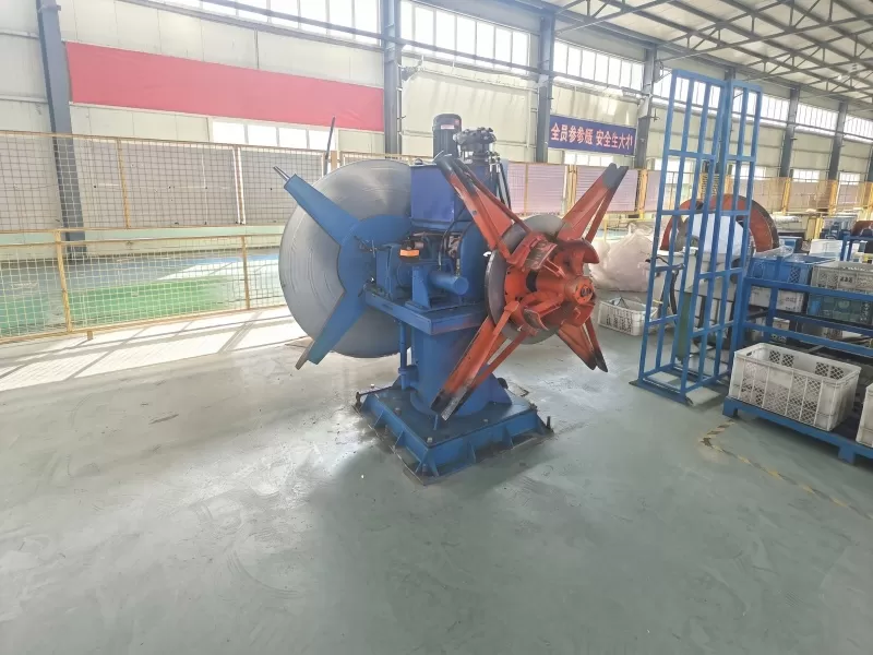
motorized decoiler distinguishes itself from passive or
brake-only designs by actively controlling strip payout speed and back tension.
This active control is essential when the mill operates at variable line speeds,
a common scenario during coil splicing or when transitioning between different
gauge materials. Passive systems often introduce tension spikes that stretch the
strip, altering its width and thickness before it enters the forming section. A
properly engineered motorized unit mitigates these variables through closed-loop
feedback, ensuring that the strip enters the shear welder or accumulator with
consistent mechanical properties.
Core Functions of a Motorized Decoiler in Coil Processing
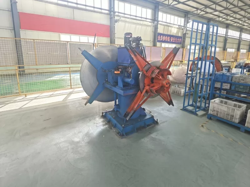
Beyond the basic task of rotating the coil, the motorized
decoiler performs several interrelated functions that directly affect
tube quality. The primary mechanical action involves supporting the coil on an
expanding mandrel, which must grip the inner diameter securely without
distorting the strip edges. Hydraulic or pneumatic expansion systems are common,
with holding torque ratings matched to the coil weight and strip width. The
drive motor, typically an AC vector or DC digital unit, provides the rotational
force required to unwind the coil at speeds that synchronize with the mill's
forming rollers.
Tension control stands as the most sophisticated aspect of decoiler
operation. The system must maintain a constant back tension across the entire
coil diameter, compensating for the changing moment of inertia as the coil
unwinds. This compensation is achieved through a combination of load cell
feedback and motor torque modulation. Some advanced designs incorporate dancer
roll assemblies that provide mechanical tension damping, while others rely
purely on electronic control loops. Both approaches have their merits, but the
selection depends on the specific strip characteristics, including yield
strength, surface finish, and edge condition. In high-strength steel
applications, the motorized decoiler must deliver higher torque
densities to overcome the material's resistance to bending, a factor that
influences motor sizing and gearbox selection.
Strip alignment and edge guidance represent another critical function. The
decoiler incorporates side guides and, in some configurations, an edge position
control system that actively steers the strip as it exits the mandrel. This
steering action prevents the strip from wandering off the centerline, which
would cause uneven loading on the forming rollers and result in helical weld
seams. For mills producing large-diameter pipe, the alignment precision must be
within ±0.5 mm over the full strip width. Achieving this accuracy requires a
rigid decoiler frame, precision-ground guide rollers, and a control system that
responds to edge detection sensors with minimal latency.
Technical Specifications and Selection Criteria
Selecting a motorized decoiler for a specific tube mill
application involves a systematic evaluation of multiple technical parameters.
The coil weight capacity is the most visible specification, but it is the
combination of weight, strip width, and outer diameter that defines the required
structural and drive capabilities. For heavy-gauge pipe production, units with a
capacity of 20 to 30 metric tons are common, while light-gauge applications may
operate with 5 to 10 ton capacities. The mandrel expansion range must
accommodate the inner diameters of the incoming coils, with typical ranges
spanning from 450 mm to 760 mm. Manufacturers often provide interchangeable
mandrel segments to cover a broader range without compromising grip force
distribution.
Drive system selection is equally critical. AC vector drives offer superior
speed regulation and energy efficiency, making them suitable for continuous
operation at variable speeds. DC digital drives, while less efficient, provide
high starting torque and are often favored for heavy-gauge applications where
initial inertia is substantial. The drive system must be paired with a braking
resistor or regenerative unit to dissipate the energy generated during
deceleration, preventing DC bus overvoltage conditions. A well-designed decoiler
drive includes software-based tension profiling that allows operators to set a
tension curve that gradually decreases as the coil diameter shrinks, maintaining
a constant strip stress level.
Structural design considerations include the base frame construction, bearing
housing rigidity, and mandrel deflection characteristics. Finite element
analysis is used by reputable manufacturers to optimize the frame geometry for
minimum deflection under full load. Bearing selection involves a trade-off
between load capacity and rotational speed, with tapered roller bearings being a
common choice for their combined radial and axial load handling. The mandrel
shaft must be heat-treated and ground to precise tolerances, as any runout
translates directly into strip oscillation that affects weld quality. For
high-speed mills operating above 100 meters per minute, the decoiler's
rotational balance becomes a critical factor, with dynamic balancing performed
to ISO grade G2.5 or better.
Control system architecture determines the decoiler's compatibility with the
broader mill automation network. Modern units employ programmable logic
controllers with Ethernet/IP or Profibus interfaces, enabling seamless
integration with the mill's line control system. This integration allows for
coordinated acceleration and deceleration profiles, reducing the mechanical
stress on the strip during line speed changes. Advanced systems incorporate
diagnostic monitoring that tracks motor current, bearing temperature, and
mandrel pressure, providing predictive maintenance alerts before component
failure occurs. SANSO's control platforms are engineered with these diagnostic
capabilities as standard, reflecting the industry's move toward condition-based
maintenance.
Integration with Tube Mill Production Lines
The physical placement of the motorized decoiler within the
production line requires careful consideration of material flow and operator
access. Typically positioned at the entry end of the line, the decoiler feeds
directly into a strip shear welder or an accumulator system. The distance
between the decoiler and the first processing station influences the strip's
catenary, or sag, which must be controlled to prevent the strip from dragging on
the floor or contacting the pit edges. A well-designed line incorporates a loop
pit or a vertical accumulator that decouples the decoiler's intermittent coil
change from the continuous mill operation.
Coil loading and unloading logistics present additional integration
challenges. Overhead cranes or coil cars are used to position the coil onto the
mandrel, with the decoiler's height and mandrel centerline carefully matched to
the crane's hook path. Automated coil loading systems, while increasing capital
cost, reduce the cycle time for coil changes and minimize the risk of operator
injury. These systems often include a coil staging area with powered rollers
that align the coil's inner diameter with the mandrel centerline before the
mandrel expands. The integration of such automation requires close coordination
between the decoiler manufacturer and the line integrator, with interface points
clearly defined in the engineering documentation.
Line speed synchronization is achieved through the decoiler's drive control,
which receives a speed reference signal from the mill's main drive. This
reference can be a simple analog signal or a digital speed setpoint transmitted
over the fieldbus network. The decoiler's speed controller adds a trim
adjustment based on the tension feedback, ensuring that the strip tension
remains constant despite variations in the mill's speed. During acceleration and
deceleration, the tension controller must anticipate the required torque
changes, a capability that distinguishes advanced drives from basic speed
followers. This anticipation is particularly important when the mill operates in
a threading mode, where slow speeds require precise tension control to prevent
strip buckling.
Common Operational Challenges and Solutions
One recurring challenge in decoiler operation is the development of strip
edge burrs or surface defects that originate from the coil's inner layers. As
the coil unwinds, the strip's surface can pick up contaminants from the
interlayer coating, which may be a rust-preventive oil or a phosphate coating.
These contaminants accumulate on the decoiler's guide rollers and pinch rolls,
eventually transferring back to the strip surface. A regular cleaning schedule
for all contact surfaces, combined with the use of rubber-covered rollers that
are less prone to scratching, mitigates this issue. Some operations install a
strip cleaning unit immediately after the decoiler to remove these contaminants
before they reach the forming section.
Mandrel grip force degradation is another common issue, particularly in
high-cycle operations where coils are changed multiple times per shift. The
hydraulic or pneumatic cylinders that expand the mandrel segments can develop
leaks or pressure losses, reducing the holding torque and allowing the coil to
slip during acceleration. This slippage not only damages the coil's inner
diameter but also causes sudden tension drops that can lead to strip fold-over.
Implementing a mandatory mandrel pressure check during each coil change, coupled
with periodic cylinder seal replacement, prevents this problem. SANSO's decoiler
designs incorporate dual pressure sensors that provide redundant readings, with
an alarm triggered when the pressure drops below a preset threshold.
Electrical noise and ground loop issues affect the tension control system's
accuracy, particularly in installations with long cable runs between the
decoiler drive and the control cabinet. Shielded cables with proper grounding
techniques are essential, as is the use of differential analog inputs that
reject common-mode noise. For installations with severe electrical interference,
fiber-optic communication between the control panel and the drive module
provides galvanic isolation, eliminating ground loop problems entirely. The
control system should also include a hardware watchdog timer that disengages the
drive if the feedback signal is lost, preventing uncontrolled acceleration.
Strip steering drift, where the strip gradually moves off-center as the coil
unwinds, is caused by a combination of factors including uneven coil winding,
mandrel wear, and guide roller misalignment. Correcting this drift requires a
systematic approach that starts with verifying the coil's winding quality, then
checking the mandrel's concentricity, and finally adjusting the side guide
positions. For persistent drift issues, retrofitting an active edge position
control system with a proportional-integral-derivative controller provides
closed-loop correction that maintains the strip's centerline within the required
tolerance. This system uses an optical or ultrasonic edge sensor to measure the
strip position, with the controller sending a correction signal to a hydraulic
steering actuator on the decoiler frame.
Maintenance Protocols for Motorized Decoiler Systems
Establishing a maintenance schedule that aligns with the decoiler's operating
hours is fundamental to minimizing unplanned downtime. Daily inspections should
include visual checks of the mandrel segments for wear, verification of the
hydraulic oil level, and a review of the drive's error log. Weekly tasks should
encompass lubrication of the bearing housings, inspection of the drive belts or
couplings, and calibration of the tension feedback sensors. Monthly maintenance
includes a thorough cleaning of the electrical cabinet, checking the tightness
of all electrical connections, and performing a functional test of the emergency
stop circuits. These scheduled activities prevent the accumulation of minor
issues that would escalate into major failures over time.
Bearing replacement is one of the most critical maintenance actions, as
bearing failure can cause catastrophic damage to the mandrel and the decoiler
frame. The bearing service life depends on the load, speed, and lubrication
quality, with typical replacements occurring after 10,000 to 15,000 operating
hours. Condition monitoring using vibration analysis and temperature sensing
allows for condition-based replacement, avoiding premature maintenance while
preventing unexpected failures. When replacing bearings, it is essential to
follow the manufacturer's torque specifications and to use the correct bearing
preload setting, as incorrect preload reduces bearing life and increases
rotational friction.
Drive system maintenance involves periodic verification of the motor's
insulation resistance, cleaning of the cooling fan and heat sinks, and
inspection of the brake resistor for signs of overheating. The motor's encoder
or resolver, which provides the speed feedback signal, should be checked for
mechanical alignment and signal integrity. Encoder misalignment, even by a
fraction of a degree, introduces speed errors that affect tension control
accuracy. For DC drives, the commutator and brushes require regular inspection,
with brush replacement scheduled when the brush length reaches the minimum
specified by the manufacturer. SANSO's service documentation provides detailed
checklists for these procedures, reflecting the company's commitment to
extending equipment life through proper maintenance.
Q: What distinguishes a motorized decoiler from a manual or
brake-type decoiler?
A: The fundamental difference lies in active torque control. A motorized
decoiler uses an electric drive motor to actively control strip payout speed and
back tension, enabling precise synchronization with the mill's line speed.
Manual decoilers rely on passive braking systems that cannot adjust for speed
variations, leading to tension fluctuations that degrade tube quality. The
motorized version also provides the ability to reverse the coil direction for
recoiling operations, a feature not available in passive designs.
Q: How do I determine the appropriate motor power rating for my
decoiler?
A: The motor power requirement is calculated based on the coil weight, strip
width, thickness, and the required line speed. A general formula involves
calculating the torque required to overcome the coil's inertia during
acceleration, adding the steady-state torque needed to maintain tension, and
applying a service factor for intermittent duty. For most tube mill
applications, the motor rating ranges from 30 kW to 150 kW. A detailed
calculation should consider the strip's yield strength and the maximum
acceleration rate of the mill.
Q: Can a motorized decoiler handle coils with damaged inner
diameters?
A: Coils with damaged inner diameters present a challenge because the mandrel
may not achieve a secure grip. Some decoiler designs include a tapered mandrel
or a segmented expansion mechanism that can accommodate slight damage. For
severe damage, a mandrel insertion guide tool can be used to ease the coil onto
the mandrel. However, consistently relying on damaged coils reduces the
decoiler's holding capacity and increases the risk of slippage, so it is
recommended to address coil damage at the receiving stage.
Q: What safety features are standard on modern motorized
decoilers?
A: Standard safety features include emergency stop pushbuttons located at the
operator station and at remote positions around the decoiler, a mandrel
interlock that prevents rotation when the mandrel is not fully expanded, and
light curtains or safety barriers that prevent operator access during operation.
Overload protection on the drive system shuts down the motor if the torque
exceeds a safe limit, while an overspeed detection circuit prevents uncontrolled
acceleration. Compliance with EN 746 or ANSI B11 standards is typical for units
supplied to regulated markets.
Q: How often should the tension calibration be
performed?
A: Tension calibration should be performed during initial commissioning and
then at scheduled intervals based on the manufacturer's recommendation,
typically every three to six months. Calibration involves applying a known
tension load to the strip and adjusting the control system's gain settings to
match the load cell readings. Additional calibration is required after any major
maintenance activity that affects the drive or the load cells, such as motor
replacement or load cell sensor replacement.
Q: What are the advantages of using a dancer roll in the decoiler
system?
A: A dancer roll provides a mechanical buffer that absorbs tension variations
from the decoiler and the mill, reducing the control system's response
requirements. The dancer arm's movement corresponds to changes in strip tension,
with the position sensor feeding a correction signal to the decoiler drive. This
arrangement is particularly beneficial in mills with frequent speed changes, as
it prevents tension spikes from reaching the forming section. The dancer roll
also compensates for the elliptical shape that some coils exhibit, which would
otherwise cause periodic tension pulsations.
Q: What is the typical lifespan of a motorized decoiler in continuous
operation?
A: With proper maintenance, a motorized decoiler can operate for 15 to 20
years in continuous production environments. The lifespan is influenced by the
operating conditions, particularly the coil weights and line speeds. Heavy-gauge
applications with frequent coil changes tend to increase wear on the mandrel
segments and the drive components, potentially reducing the service life.
Implementing a condition-based maintenance program, including regular wear
measurement and component replacement, extends the equipment's operational life
beyond the average.
The engineering and operational considerations outlined above demonstrate
that the motorized decoiler is a sophisticated piece of equipment that requires
careful selection, integration, and maintenance. For production managers
evaluating new equipment or upgrading existing lines, the focus should remain on
the specific material characteristics and production targets rather than general
specifications. SANSO provides comprehensive documentation and technical support
for its decoiler product line, assisting customers in configuring systems that
align with their operational requirements. For detailed information on product
specifications, control system options, and integration services, please contact
our engineering team with your mill parameters and production goals.