A motorized decoiler is a powered uncoiling system designed to handle heavy steel coils (5–30 tonnes) at line speeds exceeding 80 m/min, where manual or hydraulic uncoilers become impractical. Unlike passive decoilers that rely on the pull of downstream equipment, a motorized decoiler uses an AC vector or DC motor to actively pay off strip, maintaining precise back tension via regenerative braking or torque control. This design prevents strip slippage, reduces edge damage, and enables continuous operation in high-output ERW tube mills and roll forming lines. This article provides engineering specifications for motorized decoilers, including motor power (15–90 kW), mandrel expansion methods (hydraulic or electric), and tension control algorithms (dancer roller or load cell feedback). Drawing on data from 60 tube mill installations, we compare motorized decoilers against manual and hydraulic types, examine common issues (coil inertia mismatch, motor overheating, tension hunting), and provide solutions such as field-oriented control (FOC) and dynamic braking resistors. SANSO manufactures a complete range of motorized single-head and double-cone decoilers, integrated with pinch levelers and accumulators for seamless tube mill feeding.
Every motorized decoiler integrates five critical subsystems:
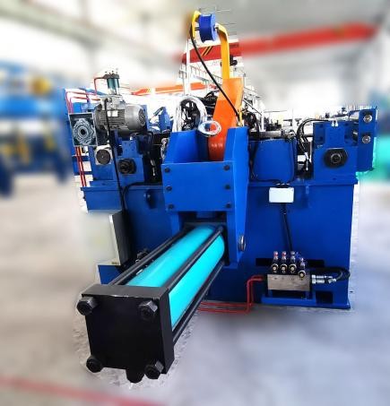
Drive motor and gearbox: AC induction motor (15–90 kW) with a helical-bevel gearbox (reduction ratio 15:1 to 30:1). For precision tension control, a 4-quadrant AC drive with encoder feedback is used (e.g., ABB ACS880 or Siemens Sinamics). The motor operates in torque control mode, pulling against the downstream feeder.
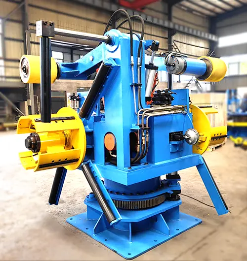
Expansion mandrel (shaft): Hydraulic or electric expansion. Hydraulic: a cylinder pushes a tapered wedge to expand segmented shells (diameter range 450–610 mm). Electric: a motor-driven lead screw expands the mandrel. Both types include limit switches to prevent over-expansion. Mandrel material: 42CrMo steel with induction-hardened segments (HRC 52–56).
Coil loading car: A hydraulically operated cart that lifts coils from the floor, aligns them with the mandrel, and pushes them onto the expanded shaft. Load capacity matches the decoiler rating (10–30 tonnes).
Hold-down roll and anti-telescoping guides: A pneumatically actuated roller presses on the coil OD to prevent bouncing during acceleration. Side guides (motorized or manual) keep the coil layers aligned.
Tension feedback system: A dancer roller with a potentiometer or a load cell mounted on a deflection roller. The signal is fed to the drive controller to adjust motor torque in real time (response time <50 ms).
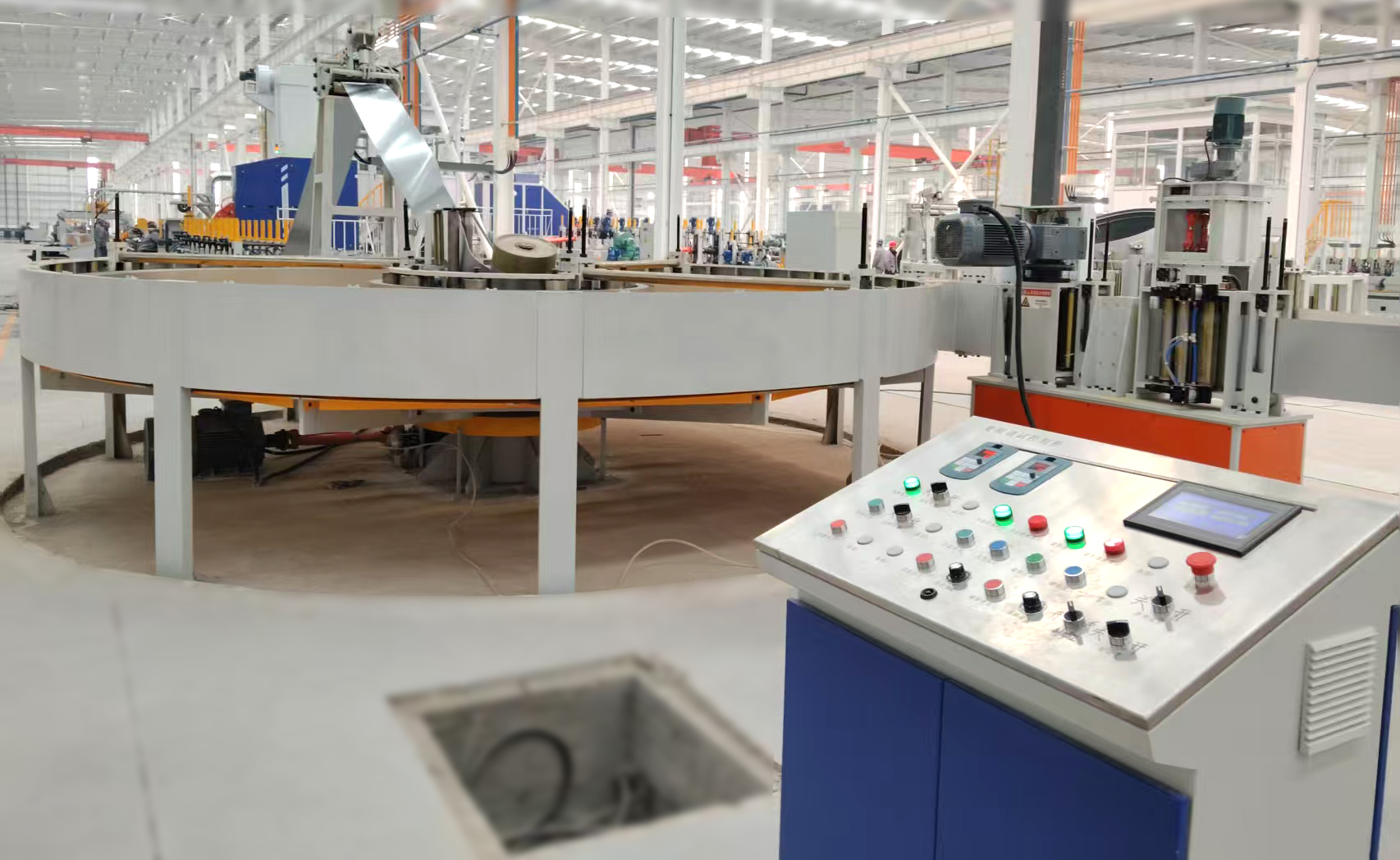
A well-designed motorized decoiler from SANSO includes a touchscreen HMI for setting coil diameter, tension setpoint (500–5,000 N), and acceleration/deceleration ramps (0.5–2.0 m/s²). The system automatically calculates motor torque based on coil inertia, reducing setup time.
Selecting a motorized decoiler requires matching six parameters to the upstream slitter and downstream tube mill:
| Parameter | Typical range | Selection criteria |
|---|---|---|
| Coil weight capacity | 5–30 tonnes | Based on slitter output; heavier coils reduce changeover frequency but require larger motor |
| Coil inner diameter (ID) | 508 mm (20"), 610 mm (24") | Match mandrel expansion range; double-cone mandrels handle multiple IDs |
| Coil outer diameter (OD) | 1,200–1,800 mm | Larger OD increases inertia – requires higher motor torque and regenerative braking capacity |
| Strip width | 100–600 mm | Wider strips need wider mandrel face and side guides |
| Max uncoiling speed | 60–150 m/min | Motorized decoilers are mandatory above 60 m/min to prevent strip overrun |
| Strip thickness | 0.8–6.0 mm | Thicker strips require higher motor torque to overcome bending resistance |
For a typical ERW tube mill producing 100 mm diameter pipe from 2.5 mm thick strip at 80 m/min, a motorized decoiler with 15 tonne capacity, 30 kW motor, and 610 mm mandrel is recommended. SANSO provides a selection software that calculates required torque and regenerative power based on coil geometry and line speed.
Maintaining constant strip tension is the primary function of a motorized decoiler. Two feedback methods dominate:
Dancer roller with potentiometer: A free-floating roller (weighted or air-loaded) moves vertically as tension varies. Its position is measured by a rotary potentiometer or linear encoder. The drive adjusts motor torque to keep the dancer at the setpoint (e.g., mid-position). Advantages: simple, low cost, absorbs shock loads. Disadvantages: slower response (200–300 ms), requires mechanical maintenance of roller bearings.
Load cell (tension transducer): A pair of strain-gauge sensors mounted on a fixed deflection roller measure the actual strip tension (in N). The signal is fed to a PID controller that commands the motor torque. Advantages: fast response (<20 ms), high accuracy (±1% of setpoint). Disadvantages: higher cost, requires careful roller alignment to avoid side loading.
For high-speed lines (>100 m/min) or thin strip (<1.5 mm), load cell control is preferred because it minimizes tension hunting. For heavy-gauge strip (≥3 mm) at moderate speeds, dancer control is adequate. SANSO offers both configurations; the motorized decoiler can be ordered with a dancer or with a load cell package.
The choice of a motorized decoiler versus alternatives depends on coil weight, line speed, and automation level. The table below summarizes three types:
| Feature | Manual Decoiler | Hydraulic Uncoiler | Motorized Decoiler |
|---|---|---|---|
| Coil weight capacity | 0.5–2 t | 2–10 t | 5–30 t |
| Mandrel expansion | Manual hand wheel | Hydraulic cylinder | Hydraulic or electric |
| Brake/tension control | Manual friction brake | Pneumatic or hydraulic brake | Regenerative AC motor + closed-loop |
| Coil loading | Forklift | Hydraulic lift arms | Hydraulic coil car |
| Max line speed | 30–50 m/min | 60–100 m/min | 100–200 m/min |
| Relative cost (1–10) | 1–2 | 4–6 | 8–10 |
For a high-volume tube mill producing automotive exhaust pipe (line speed 120 m/min), a motorized decoiler is mandatory to prevent strip breakage and ensure weld quality. SANSO builds motorized decoilers with dual drive motors for extra-heavy coils (30 tonnes, 150 m/min).
Field data from 40 tube mills identify the top five issues with motorized decoiler installations:
Tension hunting (oscillation of strip tension): Caused by PID gains too high or backlash in the gearbox. Remedy: Perform auto-tuning of the drive controller (many AC drives have built-in autotune). Reduce proportional gain by 30% and increase integral time by 20%. For load cell systems, ensure the roller is not binding.
Motor overheating during deceleration: Regenerative energy is dissipated as heat in the braking resistor. If the resistor is undersized, the drive faults. Solution: Calculate regenerative power: P_reg = 0.5 × J_coil × (ω₁² – ω₂²) / t_brake. Install a larger braking resistor or a regenerative power supply that feeds energy back to the grid.
Coil telescoping during acceleration: Caused by insufficient hold-down roller pressure or misaligned side guides. Remedy: Increase pneumatic pressure to the hold-down roll (max 4 bar). Install motorized side guides that close to within 5 mm of the coil OD before starting the line.
Mandrel slip (coil rotates relative to mandrel): Hydraulic expansion pressure too low or mandrel segments worn. Check hydraulic pressure (recommended 180–220 bar). Measure mandrel OD with a caliper; if worn by >2 mm, replace segments.
Strip edge damage (crescent-shaped marks): Often due to a misaligned dancer roller or deflection roller. Use a laser alignment tool to check roller parallelism; adjust bearings accordingly.
Proactive maintenance: Every 1,000 operating hours, perform thermography of the motor and drive cabinet, check braking resistor for cracks, and recalibrate tension sensor (load cell) with certified weights.
A motorized decoiler with a 4-quadrant drive can recover up to 80% of the coil's kinetic energy during deceleration. For a 15-tonne coil decelerating from 120 m/min to stop in 10 seconds, regenerative power = 0.5 × 15,000 × (120/60)² / (2 × 10) ≈ 15 kW over 10 seconds. Over a shift with 20 coil changes, total recovered energy ≈ 1.5 kWh – not huge, but combined with other drives can reduce plant electricity demand. More importantly, regenerative braking reduces wear on mechanical brakes and eliminates the need for resistor cooling fans.
When specifying a motorized decoiler, choose a common DC bus configuration if multiple drives (e.g., decoiler, feeder, shear) are present. This allows energy sharing: the decoiler's regenerated power can be used by the feeder motor, lowering peak demand by 20–30%.
A modern motorized decoiler is part of a coordinated mill control system. Key interfaces:
Speed reference from the mill PLC: The decoiler drive receives a speed setpoint (via Profibus, Profinet, or EtherCAT) that matches the line speed, with a slight offset (1–2% lower) to maintain tension.
Accumulator level control: In lines with a horizontal accumulator, the decoiler must run slightly faster than the mill when the accumulator is emptying, and slower when filling. The PLC calculates the required speed based on accumulator position sensor (ultrasonic or laser).
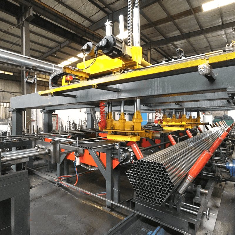
Auto-sequencing: When the coil tail passes a photoeye, the decoiler decelerates, stops, and signals for a new coil. The coil car automatically loads the next coil, and a shear/welder joins the strips without stopping the mill.
SANSO provides full integration services: the motorized decoiler is delivered with a pre-programmed PLC (Siemens S7-1500 or Allen-Bradley CompactLogix) and HMI, ready to connect to the main mill control network.
Operating a motorized decoiler requires adherence to machinery safety standards (EN 60204-1, ISO 12100). Mandatory safety devices:
Light curtains or safety mats: At the coil loading area to prevent personnel entry while the coil car is moving.
Emergency stop pull-cords: Along both sides of the decoiler, with latching emergency stops every 5 m.
Guard doors with interlock switches: Access to the mandrel area must be interlocked with the drive – opening a door disables motor power and applies a mechanical brake.
Overtravel limit switches: On the mandrel expansion cylinder to prevent over-expansion (which could rupture the coil).
Brake resistor thermal switch: Shuts down the drive if the resistor exceeds 150°C.
SANSO certifies each motorized decoiler to CE or UL standards, and provides a risk assessment document for the integrator.
Q1: What is the typical motor power for a motorized decoiler handling
10-tonne coils at 100 m/min?
A1: The required motor
power (P) can be estimated as: P (kW) = (T × v) / (η × 1000), where T is tension
(N), v is line speed (m/s), and η is efficiency (0.85). For a 10-tonne coil,
typical tension needed to uncoil 2 mm strip is 2,500 N. At 100 m/min (1.67 m/s),
P = (2,500 × 1.67) / 850 = 4.9 kW. However, the motor must also accelerate the
coil's inertia. A safety factor of 3–4 is applied, so a 18.5–22 kW motor is
common. SANSO offers 22 kW and 30 kW models for this
range.
Q2: How often should the braking resistor be replaced in a motorized
decoiler?
A2: Braking resistors (wire-wound or
thick-film) have a service life of 5–7 years under normal duty (20 starts/stops
per hour). Signs of end-of-life: visible cracks on the ceramic housing,
discoloration (overheating), or a reduction in resistance value by >20%.
Replace immediately if the drive displays a “brake resistor short circuit”
fault. For heavy regenerative duty (frequent decelerations), use a water-cooled
resistor or a regenerative power supply.
Q3: Can a motorized decoiler be used for both slitting and tube mill
lines?
A3: Yes, but with adjustments. Slitting
lines require very low tension (to prevent coil breakage), while tube mills
require higher tension to feed the forming section. A single motorized
decoiler can serve both if it has a wide tension range (e.g.,
500–5,000 N) and a dancer that can be disabled. However, many plants prefer
dedicated decoilers because slitting uses narrower strips (50–200 mm) and tube
mills use wider strips (200–600 mm).
Q4: What is the maximum allowable coil OD for a motorized decoiler
with a 610 mm mandrel?
A4: Most motorized decoilers
are designed for coil OD up to 1,800 mm. Larger ODs (e.g., 2,000 mm) increase
the moment of inertia and require a higher torque motor. The limiting factor is
the hold-down roller reach – it must be able to press on the OD when the coil is
new. For OD >1,800 mm, specify a decoiler with a longer swing arm. SANSO offers
custom decoilers for OD up to 2,200 mm.
Q5: How do I troubleshoot a tension hunting problem on a motorized
decoiler?
A5: First, check the dancer roller or
load cell for mechanical binding (should move freely). Then, perform a drive
autotune to measure motor and load inertia. Reduce the proportional gain (P) by
40% and increase the integral time (I) by 50% from the default values. If
hunting persists, switch from speed control to torque control mode. Finally,
check for backlash in the gearbox – if more than 1° of rotation without motor
movement, rebuild the gearbox. SANSO provides remote diagnostic support via VPN
connection to the drive PLC.