Industrial tube production requires a precise understanding of material
deformation, mechanical forces, and systemic alignment. To consistently
manufacture hollow sections that meet structural tolerances, manufacturing
facilities must maintain strict control over the continuous forming process. The
transformation of a flat metal strip into a perfectly closed, welded profile
depends on the synchronized performance of a roll
forming tube mill.
Understanding the physics of cold roll forming and the mechanical dynamics of
high-frequency induction welding is required to optimize line efficiency and
prevent profile defects. This analysis examines the sequential mechanics of tube
forming, diagnoses common alignment issues, and provides engineered solutions to
maximize continuous uptime.
1. The Mechanical Phases of Cold Roll Forming
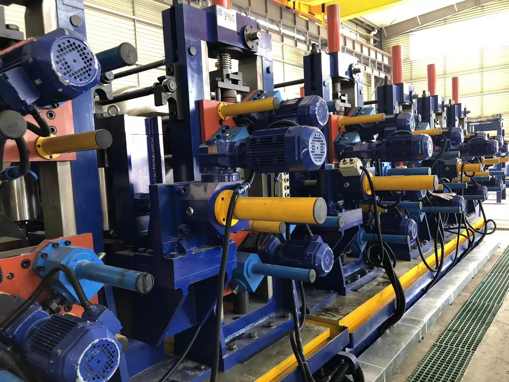
The continuous cold forming process relies on a series of paired driven rolls
that incrementally bend a flat metal strip into a closed cylindrical shape. Each
roll stand performs a mathematically calculated stage of deformation, ensuring
the material is shaped without exceeding its ultimate tensile strength. This
progression is designed using the "flower design," a CAD-generated projection of
the strip's cross-sectional changes at each individual stand.
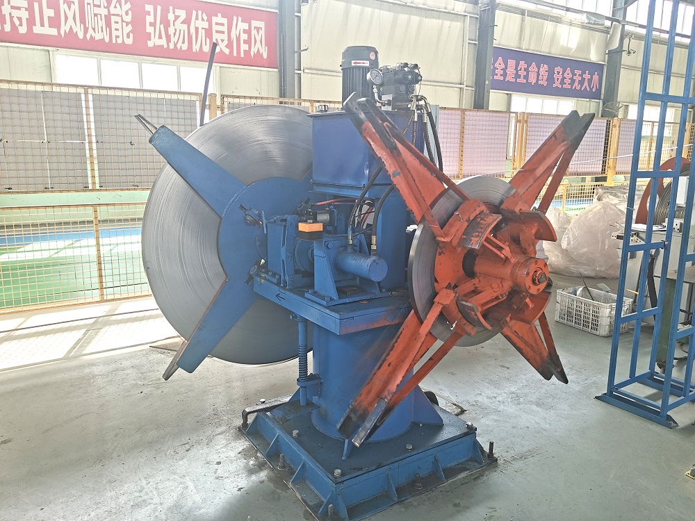
Breakdown and Prep Section
The initial stage of a roll
forming tube mill line is the breakdown section. Here, the flat
strip undergoes its primary bending. The outer edges of the strip are forced
downward or upward to establish the initial radius of curvature. The center of
the strip remains relatively flat while the outer margins receive the primary
deformation. Proper roll pass design in this section prevents edge stretch—a
condition where the strip edges are elongated beyond their elastic limit,
leading to wavy edges and poor weld presentation.
Fin-Pass Calibration
Positioned immediately prior to the welding unit, the fin-pass stands feature
rolls with central blades or fins. These fins ride inside the open seam of the
formed tube, performing several functions:
They maintain precise lateral alignment of the strip, preventing
rotation.
They burnish the strip edges, removing minor slit-edge imperfections.
They precisely calibrate the strip width and control the convergence angle
(weld vee) before the material enters the welding station.
Any fluctuation in pressure at the fin-pass section directly alters the
stability of the subsequent weld. Therefore, robust mechanical adjustments and
rigid roll stands are required to lock in the roll positions.
2. High-Frequency Induction Welding Mechanics
Once the strip has been shaped into an open cylindrical profile, the seam
must be continuously joined. High-frequency induction welding (HFIW) is the
industry standard for high-speed pipe manufacturing. This process utilizes
high-frequency alternating current (typically between 200 kHz and 400 kHz) to
heat the converging edges of the strip to a plastic, forgeable state.
An induction coil, positioned slightly upstream of the weld point, induces a
high-frequency current around the circumference of the open tube. Because of two
electromagnetic phenomena—the skin effect and the proximity effect—this current
concentrates almost entirely on the outer surfaces and along the converging "V"
shaped edges of the strip. This concentration of energy heats only the absolute
edges of the metal, minimizing the heat-affected zone (HAZ) and preserving the
mechanical properties of the surrounding tube body.
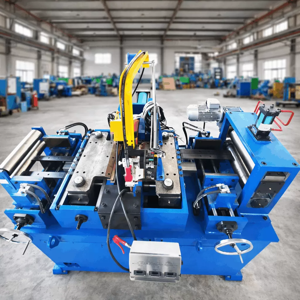
Proper design of the squeeze roll assembly within a roll
forming tube mill directly affects the final weld strength. The
squeeze rolls apply heavy mechanical force to forge the heated edges together.
This forging action forces out molten metal, oxides, and impurities, creating a
solid-state weld joint. The extruded material, known as the inside and outside
weld bead, is removed immediately after welding using stationary carbide
scarfing tools to ensure a smooth surface finish.
3. Squeeze Roll Force and Weld-Vee Geometry
The geometry of the weld-vee (the opening angle formed by the converging
strip edges) is a vital parameter in HFIW. If the weld-vee is too wide, the path
of the current becomes longer, reducing electrical efficiency and requiring
higher power to reach welding temperature. If the vee is too narrow, premature
contact can occur, leading to localized arc-outs and weld discontinuities.
The forge pressure applied by the squeeze rolls must be carefully matched to
the yield strength and wall thickness of the material. Insufficient forge
pressure results in a cast weld structure with trapped oxides, leading to seam
splitting during subsequent bending or flaring tests. Conversely, excessive
pressure forces too much plasticized material out of the joint, weakening the
weld line and accelerating squeeze roll wear.
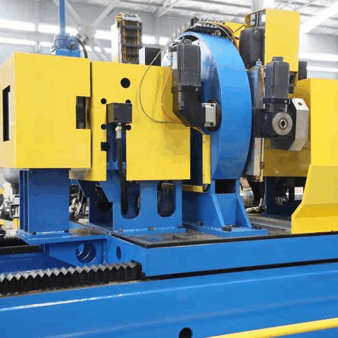
To resist these heavy radial and axial forces, the squeeze roll stands must
feature high-rigidity housings. The heavy-duty housing stands engineered by SANSO to reduce shaft
deflection ensure that forge pressure remains constant even under continuous,
high-volume production schedules.
4. Alignment Standards and Tooling Wear Management
Maintaining a stable, continuous line requires precise alignment across all
forming, welding, and sizing stands. Any misalignment of the rolls relative to
the mill's theoretical centerline introduces unwanted twisting, cambering, and
marking on the finished tube.
Standard Procedures for Mill Alignment
Bottom-Line Verification: The bottom rolls of all stands
must be aligned to a consistent, level horizontal plane. This "bottom line" acts
as the reference datum for all vertical adjustments of the top rolls.
Centerline Calibration: A wire or laser alignment system
must pass through the exact lateral center of every roll stand to ensure there
is no horizontal offset from the entry guide to the cutoff system.
Shaft Parallelism: The top and bottom roll shafts must
remain strictly parallel under load to prevent uneven strip tracking and
asymmetrical edge deformation.
Tooling wear is a natural consequence of the continuous contact between the
steel strip and the roll profiles. To reduce wear rates and prevent material
pick-up (where small particles of the strip adhere to the roll surface, causing
surface scoring), manufacturers utilize high-quality tool steels such as D2 or
Cr12MoV, heat-treated to a hardness of 58-62 HRC. Continuous lubrication with
high-efficiency synthetic water-soluble coolants is also required to reduce
friction and dissipate heat generated during cold deformation.
5. Sizing, Straightening, and Profile Conversion
After the welding and scarfing processes, the tube passes through a cooling
trough where water sprays lower its temperature to near-ambient levels. This
cooling stage is necessary before the tube enters the sizing section, as thermal
contraction would otherwise alter the final dimensions.
The sizing section typically consists of three or four sizing stands and one
or two Turk’s head units. The primary function of this section is to bring the
cooled round tube to its final outside diameter and roundness tolerances.
Additionally, the sizing section is responsible for converting round mother
tubes into square, rectangular, or special profile shapes.
The development of the direct square roll
forming tube mill has mitigated several process challenges
associated with structural profile manufacturing. Traditional methods form a
round tube first and then deform it into a square in the sizing section. This
two-step process can concentrate stress at the corners, increasing the risk of
cracking, especially when working with high-strength steels. Direct square
forming shapes the strip directly into a square profile, avoiding these
localized stresses and producing sharper, more uniform corners.
Managing springback is a major engineering focus in this stage. Springback
occurs when the elastic recovery of the steel opposes the plastic deformation
applied by the rolls. Tooling designers must overbend the profile beyond the
target dimensions to compensate for this recovery, ensuring the finished tube
meets the specified tolerances after exiting the final stand.
6. Improving Mill Runtime and Changeover Efficiency
For high-capacity manufacturing lines, minimizing downtime during product
changeovers is a major operational challenge. Traditional tooling changes
require operators to manually remove each roll from its shaft, a labor-intensive
process that can keep the mill offline for hours.
To address this bottleneck, advanced lines utilize quick-change systems, such
as rafted roll stands. In a rafted mill configuration, the forming stands are
mounted on sub-plates (rafts) that can be disconnected from the main drive
couplings and lifted out of the mill bed as a single unit using an overhead
crane. Pre-assembled rafts with the new tooling set are then dropped into place,
reducing the changeover time from hours to minutes.
The quick-change raft systems offered by SANSO optimize
changeover procedures, enabling manufacturers to transition between different
profile dimensions rapidly and protect overall equipment effectiveness.
7. Key Factors in Equipment Specification
When selecting or configuring a new production line, engineering departments
must evaluate several system parameters to ensure the machinery matches their
specific material range and production output targets:
| Parameter | Primary Engineering Consideration | Impact on Quality |
|---|
| Shaft Diameter & Motor Power | Must resist maximum torque and deflection when forming high-thickness
materials. | Prevents thickness variations and uneven shape calibration. |
| Weld Speed and HF Power | Higher speeds require more kW of high-frequency power to reach the forge
temperature. | Maintains a uniform weld seam without cold welds or overheating. |
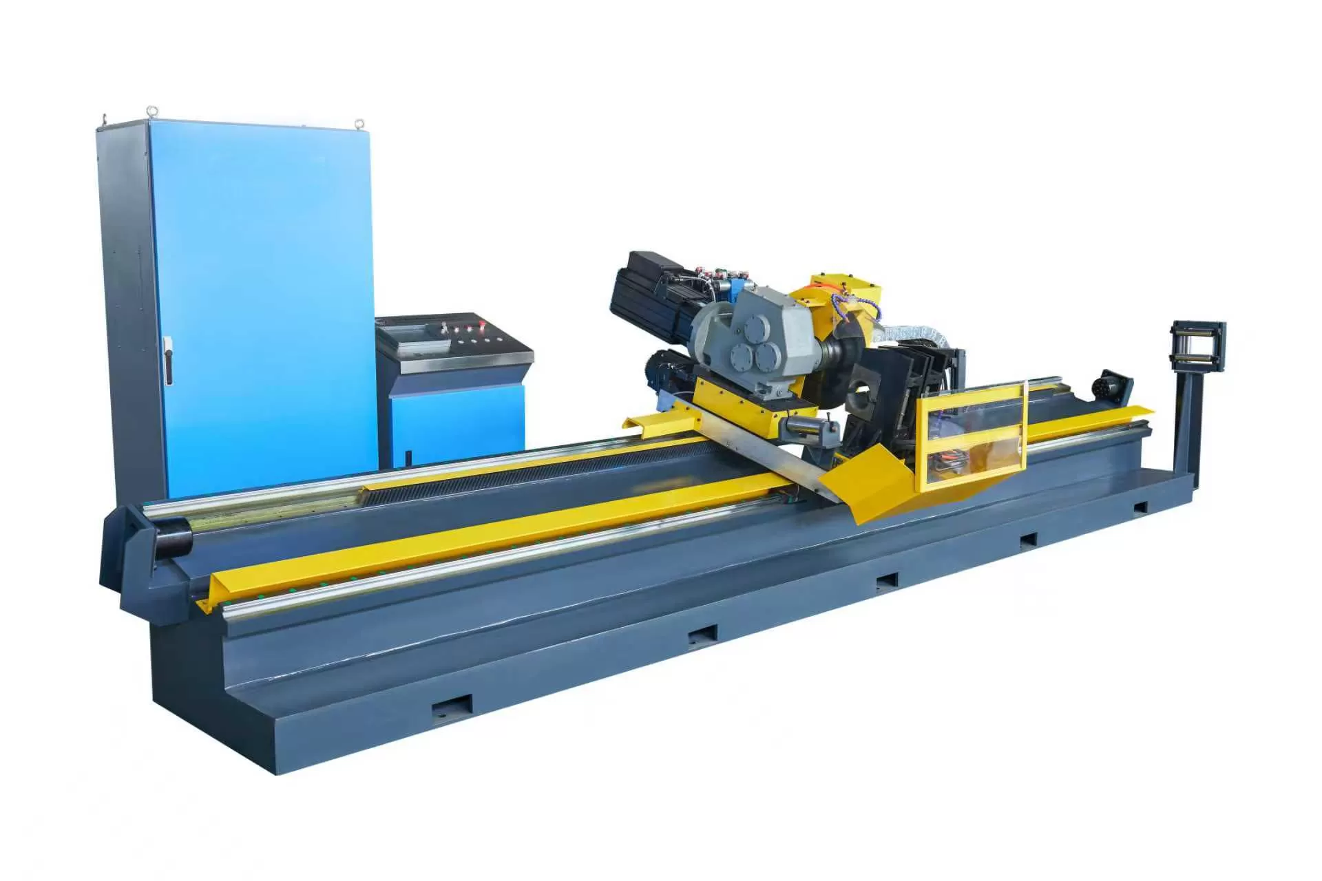
| Cutoff System Integration | Flying cold saws or friction saws must synchronize with the mill line
speed. | Ensures burr-free cuts and accurate length
tolerances. |
An accurately configured line ensures that the deformation energy matches the
yield point of the heaviest wall thickness profile, preventing motor overloading
and maintaining stable run speeds across all production runs.
Frequently Asked Questions (FAQ)
Q1: What causes unstable welding in high-frequency tube production?
A1: Unstable welding is usually caused by irregularities in
the weld-vee angle, inconsistent strip edge quality, or fluctuating
high-frequency power. If the strip edges are wavy due to excessive edge stretch
in the forming section, the V-point where the edges meet will shift back and
forth, causing localized cold welds or burn-through. Maintaining correct
fin-pass adjustment and squeeze roll alignment is vital to stabilize the
V-point.
Q2: How does roll pass design affect the longevity of the tooling?
A2: A well-engineered roll pass design distributes the
deformation workload evenly across all available forming stands. If a single
stand is required to perform too much work, it experiences high friction and
wear. Proper design also limits the relative sliding velocity between the roll
surface and the steel strip, which is the primary cause of abrasive wear on the
tooling profiles.
Q3: Why does a direct square roll
forming tube mill produce better corner radiuses than traditional
sizing methods?
A3: Direct square forming distributes the bending stresses
more evenly across the width of the strip during the early forming stages. In
contrast, traditional sizing forces a fully welded round tube into a square,
placing extreme localized stress on the corners. This corner strain can lead to
material thinning, micro-cracking, and uneven corner radiuses.
Q4: Why is mill alignment verification necessary?
A4: Even minor misalignment of a few tenths of a millimeter
can introduce complex stresses into the steel strip. This results in structural
defects such as tube twist (where the square profile rotates along its axis),
camber (axial bowing), or surface marking from the rolls. Regular centerline and
bottom-line laser verifications prevent these issues and reduce scrap rates.
Q5: How does high-strength steel affect the forming machine
requirements?
A5: High-strength low-alloy (HSLA) steels have high yield
strengths and severe springback characteristics. Forming these materials
requires significantly higher motor power, heavier shaft diameters, and
reinforced housing stands to withstand the increased forming forces. Tooling
profiles must also feature specialized overbend designs to compensate for the
greater elastic recovery of the material.
Industry Cooperation and Inquiry
Maximizing the efficiency of a high-frequency tube line requires specialized
engineering expertise and high-precision machinery. For manufacturers seeking to
upgrade existing lines or establish a new high-precision production facility, we
invite you to consult with the engineering specialists at SANSO to configure
custom equipment layouts. Contact our office today with your material
specifications and profile dimensions to receive a comprehensive technical
proposal.