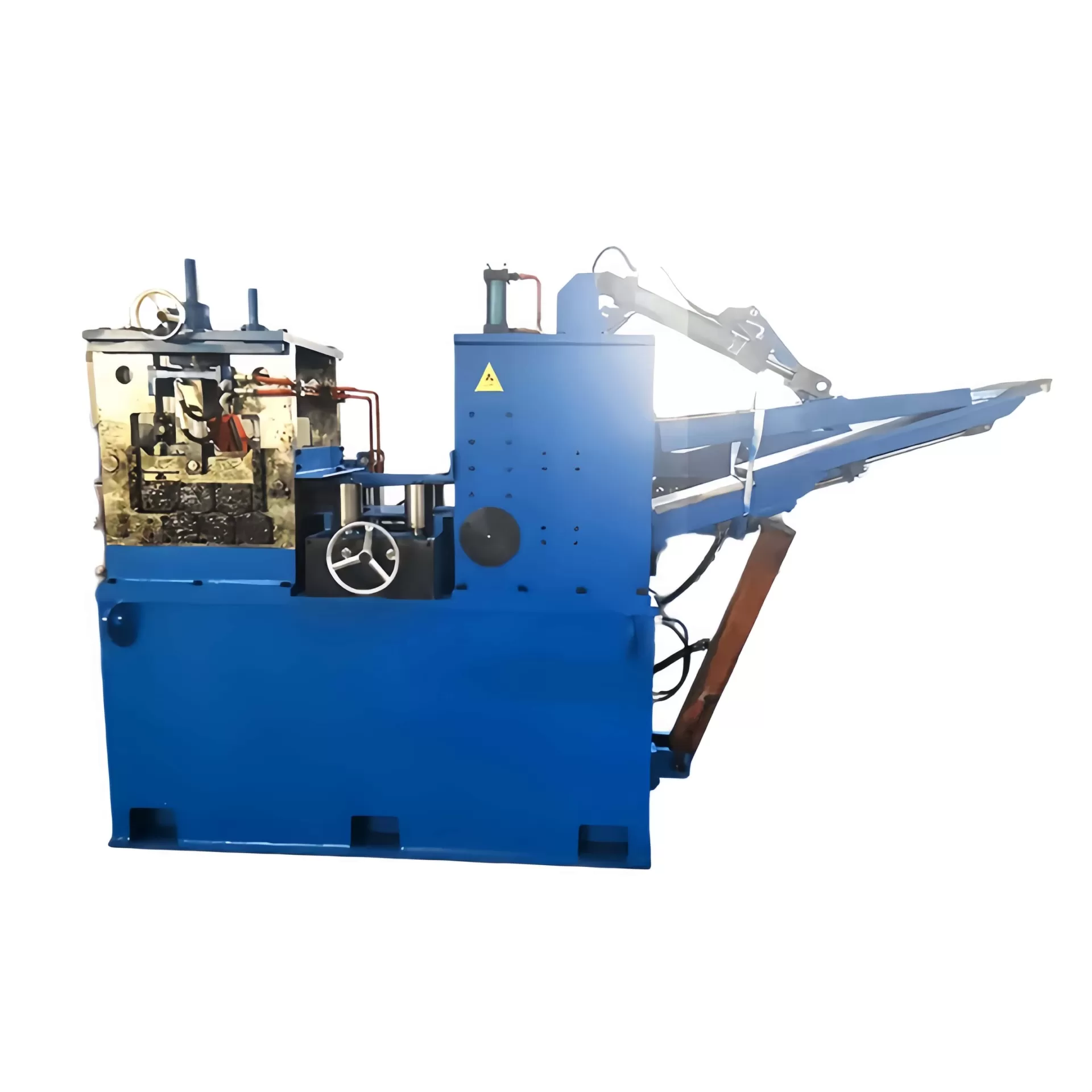
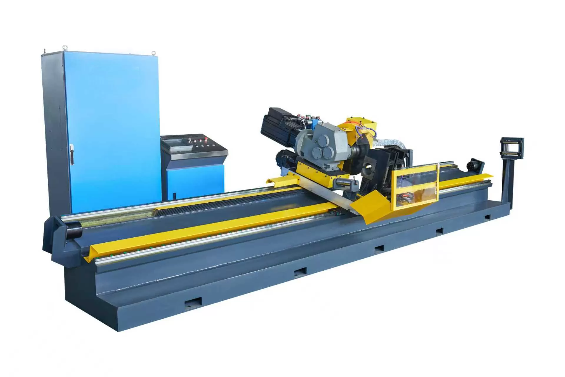
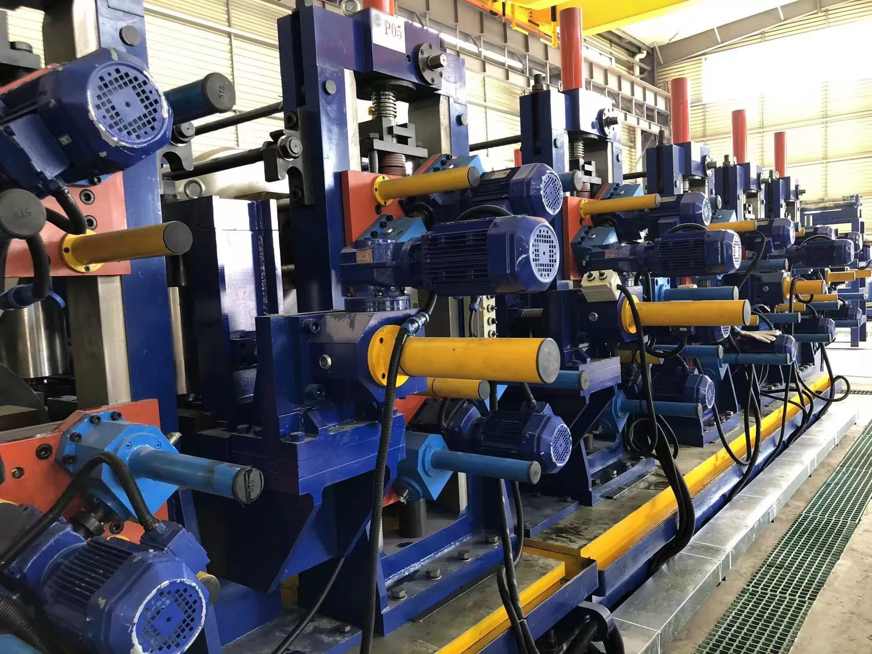
High-volume carbon steel pipe manufacturing demands continuous, reliable processing lines where downtime immediately impacts operational metrics. The cut-off stage, particularly when employing flying cold saws on continuous tube mills, represents a primary bottleneck if not properly calibrated. To maintain clean, burr-free cuts without interrupting line speeds, structural and mechanical parameters must be balanced. Transitioning from traditional friction cutting to cold sawing has significantly improved cut edge quality and metallurgical integrity at the tube ends.
Achieving these outcomes depends heavily on the interface between the cutting tool and the workpiece. The mechanical performance of a industrial-grade tct saw blade is not merely a matter of rotational speed; it requires a systematic understanding of metallurgy, plate tensioning, tooth geometry, and machine synchronization. By addressing these variables, pipe manufacturers can maintain stable production runs and reduce structural deformation during high-speed processing.
Metallurgical Composition and Tooth Geometry of Tungsten Carbide Tips
The cutting edge of a modern industrial cold saw blade relies on Cemented Carbide (WC-Co) composite tips brazed to a high-strength alloy steel core. The ratio of tungsten carbide grain size to cobalt binder content determines the mechanical properties of the tip. For steel pipe cutting applications, where the blade encounters interrupted cuts and high-impact forces upon entering the tube wall, a specific balance between hardness and fracture toughness is required.
Cobalt Binder Ratio: A cobalt content of 8% to 11% is typical for pipe-cutting applications. This range provides the necessary impact resistance to withstand the shock of cutting through welded seams without suffering brittle fractures.
Sub-Micron Grain Size: Utilizing WC grains in the 0.6 to 1.0 micrometer range preserves edge sharpness while preventing rapid abrasive wear from the hard iron carbides present in structural steel.
Tooth Profiles (TCG vs. ATB): The Triple Chip Grind (TCG) configuration is standard for steel cutting. The chamfered lead tooth removes the center section of the material, while the flat trailing tooth cleans the remaining corners. This distributes the chip load evenly, lowering lateral cutting forces.
Rake and Clearance Angles: Negative or neutral rake angles (typically 0° to -6°) are utilized to prevent the blade from aggressively grabbing the tube wall. This angle stabilizes the plunge rate and protects the carbide tips from shearing under high pressure.
Once the metallurgical composition is determined, the physical geometry of the teeth must be configured to accommodate the specific wall thickness of the tube. Incorrect tooth pitch can lead to chip packing, which causes immediate tooth breakage. When selecting tooling, engineers at SANSO suggest that matching the blade diameter and tooth count to the tube diameter ensures that at least two to three teeth are engaged in the cut simultaneously, preventing tooth straddling and subsequent tip damage.
Mechanical Stability of the Blade Plate
The alloy steel plate supporting the carbide tips must resist deflection under both centrifugal forces and the axial forces generated during feed cycles. Most high-performance blade bodies are manufactured from 75Cr1 tool steel, heat-treated to a hardness of 44 to 46 HRC. This hardness range provides the elasticity required to absorb vibrations while maintaining structural flatness.
To ensure steady rotation at high surface feet per minute (SFM), the steel plate undergoes a precise tensioning process. Tensioning introduces controlled internal stresses that counteract the expansion of the outer rim as it heats up during operation. Without proper tensioning, the blade will develop lateral runout (wobble), resulting in wider kerfs, excessive material waste, and premature wear of the carbide tips.
Mechanical vibration is further controlled by laser-cutting expansion slots into the blade body. These slots allow the outer rim to expand thermally without warping the main plate. Many modern designs fill these slots with polyurethane or copper plugs to absorb acoustic resonance, dampening vibrations that would otherwise transfer back to the spindle bearings of the flying cut-off carriage.
Operational Dynamics on Flying Cut-Off Systems
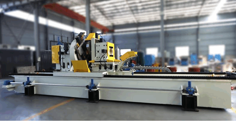
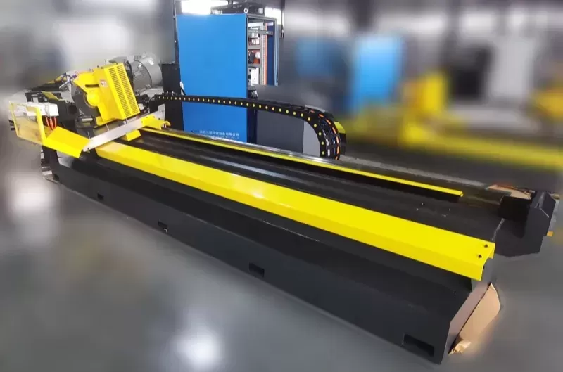
Integrating a high-performance cutting tool into a continuous production line requires coordination with the tube mill flying shear carriage. The carriage must accelerate to match the speed of the tube exactly before the blade begins its plunge. Any speed differential between the carriage and the pipe introduces immense axial force onto the blade plate, causing rapid deformation or complete tool failure.
The plunge feed rate must be dynamic rather than constant. When a tct saw blade first contacts the curved surface of a round tube, the contact area is highly concentrated. If the feed rate is too aggressive during this initial penetration phase, the sudden chip load will fracture the lead teeth. A variable feed profile, which slows down during entry and exit while accelerating through the hollow center section, reduces mechanical strain on both the blade and the spindle motor.
By integrating robust flying cold saws from manufacturers like SANSO, pipe producers can manage these complex movement profiles. Controlling the entry velocity and maintaining a consistent feed per tooth (typically 0.03 to 0.06 mm/tooth) prevents thermal build-up and maintains structural control over the entire cutting cycle.
Analyzing and Preventing Common Tool Degradation Modes
Understanding how cutting tools degrade under continuous load allows operators to implement preventive maintenance before cataclysmic tool failure occurs. In steel tube milling, wear patterns are rarely uniform, and monitoring them provides insight into the mechanical health of the entire line.
Micro-chipping along the cutting edge is often the first sign of instability. This is usually caused by mechanical shock, which can stem from backlash in the gearboxes of the flying shear, loose tube clamping jaws, or inadequate entry-speed dampening. If left unaddressed, micro-chips grow into macro-fractures, eventually shearing off the entire carbide tip and damaging adjacent teeth.
Thermal cracking, characterized by vertical hairline fractures perpendicular to the cutting edge, indicates poor thermal management. This occurs when the cooling cycle is inconsistent. Cold sawing relies on either flood coolant or Minimum Quantity Lubrication (MQL). If the coolant spray is misdirected, the tip undergoes rapid heating during the cut and rapid cooling when it exits the tube, leading to thermal shock. Constant lubrication and proper nozzle alignment are necessary to prevent this thermal cycling fatigue.
Adapting Tool Specifications to Steel Grades and Wall Thicknesses
There is no single blade configuration that accommodates every pipe manufacturing run. Correctly pairing the cutting tool with the specific carbon steel grade and geometry of the workpiece is necessary for operational efficiency. Standard structural steels (like A36 or A1011) present different machining properties compared to high-strength low-alloy (HSLA) steels used in automotive or API-grade pipeline manufacturing.
For thin-walled tubing, the pitch must be small enough to avoid catching the tooth on the thin edge of the cut. Conversely, when cutting heavy-walled structural hollow sections, a larger pitch with deeper gullets is required to carry the substantial chips out of the cut zone. If the gullet is too small, the chip compresses, friction increases, and the temperature rises beyond the thermal threshold of the cobalt binder.
Consequently, selecting the appropriate tct saw blade configuration depends heavily on matching tooth geometry to these physical parameters. Harder steel grades require lower peripheral cutting speeds to control heat, whereas softer, low-carbon steels can be cut at higher speeds but require specialized chip breakers to prevent long, continuous ribbons of metal from bird-nesting around the spindle.

Performance Benchmarks for Continuous Production Lines
Establishing clear KPIs for the cut-off station helps manufacturers maintain predictable output. Monitoring parameters such as squareness of the cut, burr height, and the number of cuts achieved per tool change provides the necessary data to adjust feed rates and rotation speeds.
A well-maintained cold saw setup should produce cut ends requiring minimal deburring or facing. If burr height starts to exceed 0.2 mm, it usually indicates that the carbide tips have lost their sharp cutting edge and are now plowing through the material rather than shearing it. Keeping a detailed log for each tct saw blade helps in predicting when to pull the tool for sharpening, preventing damage to the steel plate body.
Additionally, keeping radial and axial runout tolerances tight on the spindle itself is important. Even if the blade is manufactured within tight tolerances, spindle wear or incorrect mounting plate torque can introduce runout, leading to uneven tooth wear. When mounting a new tct saw blade onto the spindle, operators must ensure that all mating surfaces are free of debris, as even a tiny particle can cause significant runout at the blades outer diameter.
Engineering Inquiries and Support
To match your specific tube mill speeds, steel grades, and wall thickness configurations with the proper cutting setups, detailed engineering parameters must be assessed. The technical development teams at SANSO utilize finite element analysis to recommend the correct tooth profiles, plate thickness, and carbide grades for industrial operations.
For custom configurations, machine compatibility assessments, or performance troubleshooting, please contact our analytical division with your production line specifications. Providing detailed information regarding your tube diameters, wall thickness ranges, and current carriage drive setups will allow our engineering team to provide a precise tool recommendation.
Frequently Asked Questions
Q1: What is the main cause of rapid tooth chipping when cutting galvanized steel tubes?
A1: Galvanized steel tubes present a layer of zinc that can clog the clearance angles of the carbide tips, leading to adhesive wear and galling. When zinc adheres to the tooth, it increases friction and cutting forces, causing micro-vibrations that lead to chipping. Using a specific coating (like TiAlN) or adapting the tooth geometry with a negative rake angle helps prevent the zinc from bonding to the carbide surface.
Q2: How does cold sawing compare to friction sawing in terms of tube end metallurgy?
A2: Friction sawing relies on high rotational speeds to melt the steel in the cut zone, which creates a large heat-affected zone (HAZ) and leaves a heavy, hardened burr. Cold sawing with a carbide-tipped blade rotates at a much lower speed and uses a high feed rate, ensuring that the heat generated is transferred to the chip rather than the tube. This keeps the cut end cool, preserving the mechanical properties of the steel and leaving a clean, low-burr finish.
Q3: What is the recommended feed per tooth for cutting carbon steel structural pipes?
A3: For carbon steel structural pipes, the recommended feed per tooth (Sz) generally ranges from 0.03 mm to 0.07 mm per tooth. The exact value depends on the wall thickness and the steel grade. A feed rate that is too low causes rubbing instead of cutting, leading to rapid abrasive wear. A feed rate that is too high overloads the carbide tip, resulting in mechanical fractures.
Q4: How many times can a industrial-grade TCT blade be sharpened before it must be decommissioned?
A4: An industrial blade can typically be sharpened 10 to 15 times, provided that the plate body has not suffered severe lateral runout or thermal warping. The number of sharpening cycles depends on the depth of the wear land. If the blade is run past its wear limit and chips the carbide tips deeply, more material must be ground away during sharpening, reducing the overall lifespan of the tool.
Q5: Why is MQL preferred over flood coolant in certain flying cut-off applications?
A5: Minimum Quantity Lubrication (MQL) delivers a precise micro-dosage of high-performance oil mixed with compressed air directly to the cutting edge. This provides excellent lubrication, reducing friction and preventing chip welding. In flying cut-off systems, MQL reduces the mess associated with flood coolant, prevents water ingress into the carriage electronics, and ensures that the finished tubes do not require extensive washing before subsequent processing or coating steps.