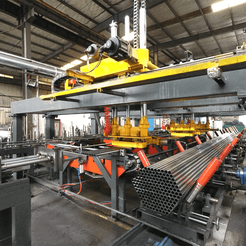
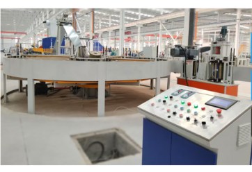
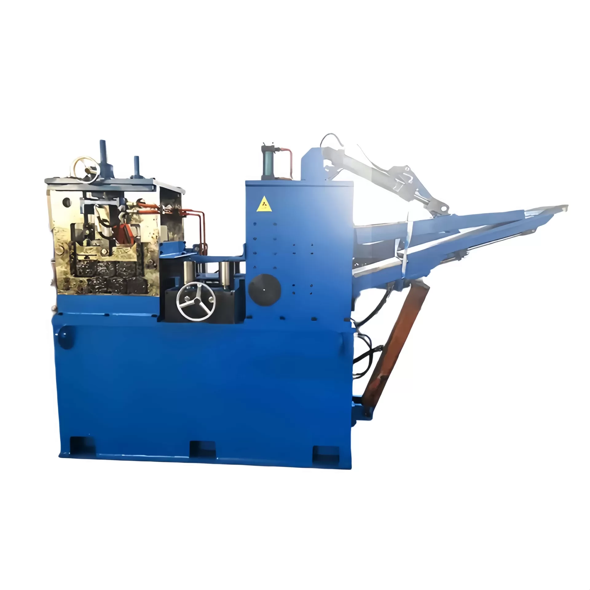
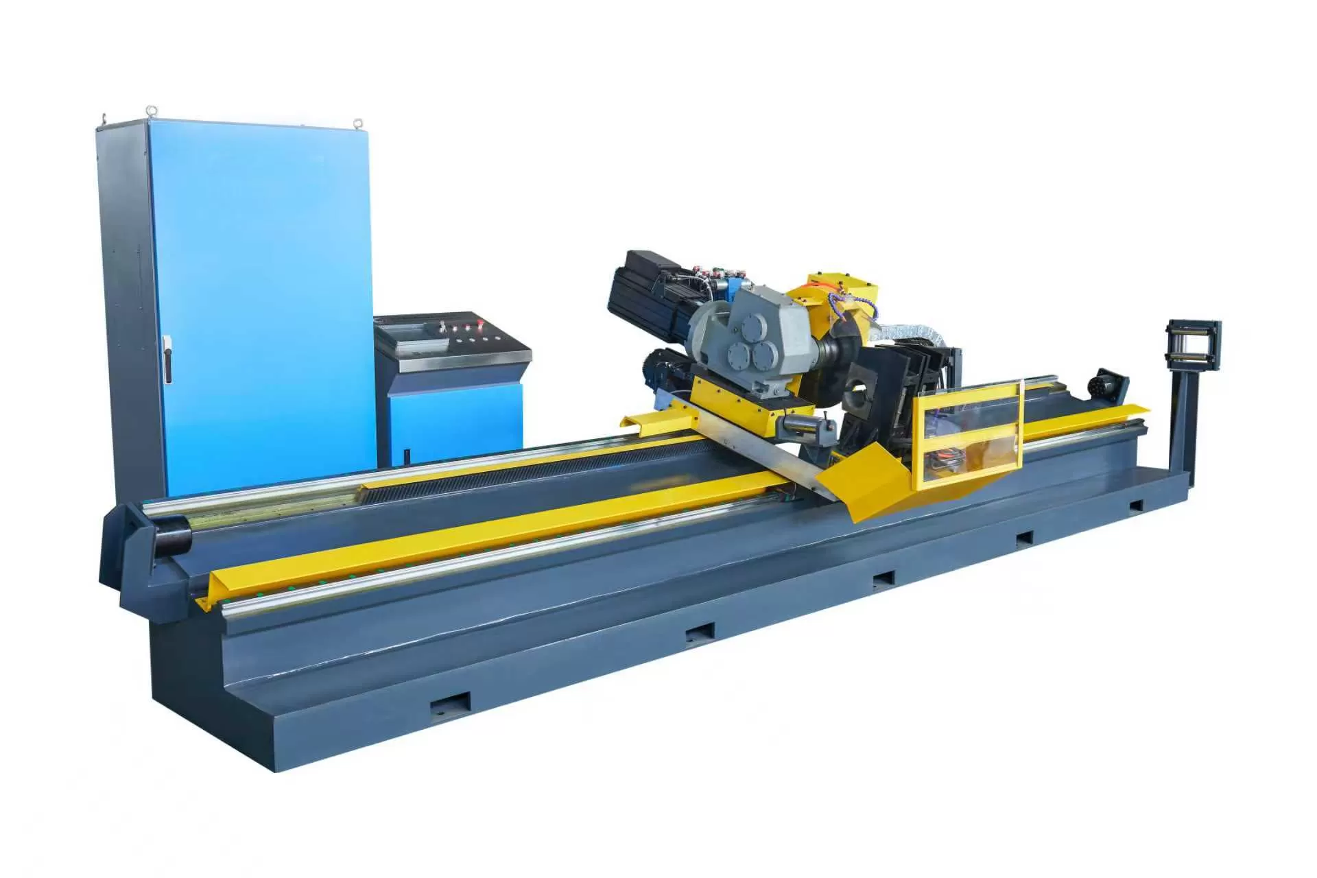
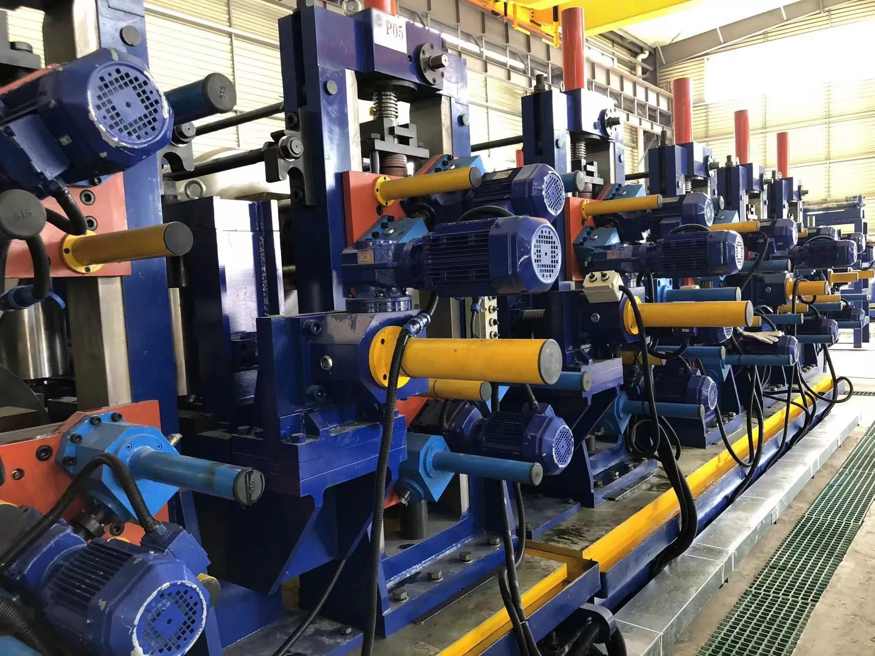
In modern welded pipe manufacturing, the tube rolling mill serves as the core production asset
that converts flat steel strip into precision tubular products. Unlike extrusion
or seamless processes, roll forming through progressive stands applies
incremental bending forces to achieve the desired circular or custom profile.
This article dissects the engineering principles, common failure points, process
control methodologies, and advanced solutions for high-speed tube mills, with an
emphasis on practical data and metallurgical considerations.
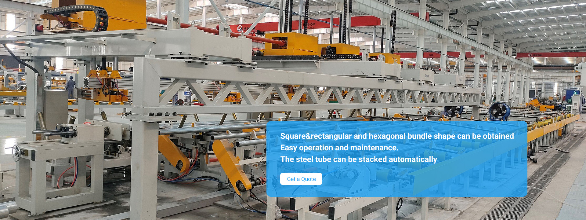
1. Core Architecture of a Modern Tube Rolling Mill
A high-performance tube production line integrates several interdependent
zones. The tube rolling mill layout typically comprises:
Uncoiling & strip preparation: Hydraulic payoffs with
edge trimming and strip accumulator.
Entry guiding & leveling: Roller levelers to eliminate
residual stresses and camber.
Breakdown section: 4–8 horizontal roll stands with vertical
idle rolls to initiate edge bending.
Cluster / forming section: Finer pitch stands where the
open seam approaches a circular shape.
Fin-pass & welding box: Squeeze rolls that close the
edges for high-frequency induction or contact welding.
Sizing & straightening: 4–6 stands to achieve final
outer diameter, roundness, and residual stress relief.
Each stand utilizes specific roll tooling geometries (flower pattern)
calculated via finite element analysis to avoid edge waves or central buckling.
The material of rolls—typically D2 tool steel, chromium‑plated surfaces, or
tungsten carbide for high‑wear applications—directly influences maintenance
intervals and product surface quality.
2. Key Performance Parameters and Process Windows
Operators of a tube rolling mill must control multiple interdependent
variables to achieve consistent weld integrity and dimensional tolerances (ASTM
A500 or API 5L). Critical parameters include:
Strip width tolerance: ±0.5 mm for repeatable edge
alignment before welding.
Roll gap calibration: Closed‑loop screw‑down systems with
position feedback (resolution ≤0.01 mm).
Welding V-angle: 3° to 7° for high-frequency induction,
influencing heat concentration.
Strip travel speed: Ranges from 30 m/min for heavy-wall oil
pipes up to 180 m/min for light structural tubing.
Sizing pass reduction: 0.3%–0.8% OD reduction to eliminate
springback and polygon effects.
Real‑time monitoring of mill load, motor current, and strip temperature
(pyrometers after welding) allows closed‑loop adjustments. Modern lines
integrate automatic wall thickness tracking via ultrasonic sensors placed after
the sizing section.
3. Industry Pain Points and Root Cause Analysis
Even well‑designed tube rolling mills encounter specific defects that impact
yield and scrap rates. Below are the most frequent failures with their
engineering origins:
3.1 Edge waves and longi bow
Cause: Incorrect flower design leading to excessive edge
stretch or insufficient middle fiber compression. Also caused by roll
misalignment exceeding 0.1 mm across stands.
Solution: Re‑engineer roll contours with spline interpolation. Implement laser alignment
checks after every tooling change.
3.2 Weld seam offset (high/low weld)
Cause: Uneven closing pressure from fin‑pass rolls or
lateral strip wandering.
Solution: Add servo‑controlled edge
guides upstream and hydraulic weld box with centering sensors. Some mills employ
camera-based seam tracking coupled with hydraulic roll adjusting cylinders.
3.3 Inner flash / I.D. burr irregularities
Cause: Inconsistent squeeze force or worn welding roll
surfaces.
Solution: Utilize linear force sensors on squeeze
stands and schedule roll re‑grinding every 400–600 operating hours depending on
material grade (e.g., for API X42 pipe).
For manufacturers facing multiple product changeovers daily, SANSO offers modular
quick‑change cartridges that reduce downtime by 65% compared to traditional
bolt‑on rolls. Their cassette design pre‑aligns roll tooling offline,
maintaining repeatability for precision tube dimensions.
4. Solutions for High‑Precision Tube Production
To overcome the limitations of conventional mills, advanced tube rolling mill platforms incorporate the following
engineering upgrades:
Hydrostatic roll bearings: Eliminate clearance‑related
radial runout, improving OD tolerance to ±0.08 mm for automotive tubing.
Direct drive servomotors per stand: Independent speed
control prevents inter‑stand tension variations, which cause wall thinning or
thickening. Speed synchronization error below 0.05%.
Integrated weld seam annealing: Inline induction heating
downstream of sizing reduces residual stresses from forming, preventing cracking
during secondary bending operations.
Automatic roll lubrication systems: Micro‑dosing oil/air
mist reduces friction and roll wear, particularly for stainless steel or
galvanized strip.
When producing square or rectangular hollow sections, a dedicated forming
approach is required. SANSO engineering solutions
employ direct forming technology, eliminating the round‑to‑square reshaping
step. This reduces forming forces and improves corner fill without overstressing
the base material.
5. Advanced Tooling Design and Flower Pattern Optimization
The most critical intellectual property for any tube rolling
mill lies in the roll flower – the sequence of cross‑sectional
deformations from flat strip to finished tube. Optimized flowers achieve uniform
strain distribution, reducing work hardening and mill power consumption. Modern
methods include:
COPRA® or similar FEA simulations: Predict edge elongation
and recommend intermediate roll profiles.
Variable width forming (flexible roll forming): Allows one
tool set to cover a range of tube diameters (e.g., 50–80 mm OD) by repositioning
roll flanges via CNC‑controlled axial movers.
Texture and coatings: Titanium nitride (TiN) or chromium
carbon coatings on roll surfaces reduce adhesive wear when forming
aluminum‑killed steel or pre‑painted materials.
Proper flower design also includes the fin‑pass zone where the seam edges
first contact. An incorrect V‑angle or roll shoulder geometry leads to cold lap
defects or insufficient weld penetration. Data from mills indicate that
laser‑welded rolls with cryogenically treated surfaces offer 40% longer life in
high‑silicon steel applications.
Preventive maintenance ensures consistent product tolerances and avoids
unplanned shutdowns. Key focus areas for a tube rolling mill include:
Roll geometry audit: Monthly 3D scanning of roll passes to
detect wear beyond 0.15 mm depth; scheduled re‑profiling using CNC roll
lathes.
Spindle and universal joint lubrication: High‑frequency
greasing intervals (every 150 operating hours) to prevent backlash that causes
marking on tube surface.
Housing and bearing clearance checks: Dial gauge
measurement of roll stack vertical play—should be <0.03 mm for precision
mills.
Strip cleanliness monitoring: Inline brushes and vacuum
systems to avoid debris embedment into rolls, which creates longitudinal
scratches.
For integrated mills, SANSO provides remote digital
assistance for roll pass setup, where operators share real‑time mill data
(vibration, load, temperature) to diagnose precursor signs of bearing failure or
roll slippage. This proactive approach cuts repair costs and extends roll
life.
7. Sizing and Straightening: Final Dimensional Control
After welding and scarfing, the tube enters the sizing section. Here,
tube rolling mill stands apply small reductions (generally
0.2–0.5% of OD) to achieve final diameter and roundness. Common sizing
configurations include:
Two‑roll turks head units: For heavy‑wall tubes (up to 12
mm WT) to correct ovality.
Four‑roll or universal sizing mills: Independent horizontal
and vertical rolls that handle square/rectangle sections without twisting.
Stretch reducing mills (optional): Tandem stands that
reduce diameter while increasing length; suitable for seamless‑like surface
finish but rarely used in direct forming lines.
Straightening is achieved by cross‑roll or 6‑roll rotary straighteners.
Correct straightener roll settings require knowledge of the tube’s yield
strength and residual stress profile. Over‑straightening introduces waviness;
under‑straightening leaves a helix mark.
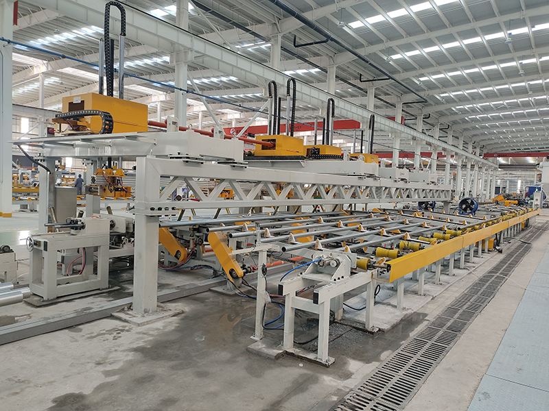
8. Emerging Capabilities: Automation and Data Logging
Industry 4.0 integration in tube rolling platforms enables real‑time
statistical process control (SPC). Modern lines use edge cameras, laser
micrometers, and eddy current flaw detectors feeding data to a central PLC.
Machine learning models (applied to historical data) can predict strip edge
misalignment 12 seconds before the weld box, allowing automatic roll adjustment.
Such systems reduce scrap by up to 18% in high‑speed lines.
Additionally, digital twins of the roll forming process allow engineers to
simulate tooling changes offline. This eliminates trial‑and‑error runs on the
physical mill, saving both material and setup hours.
Frequently Asked Questions (FAQ)
Q1: What is the typical
production tolerance achievable with a modern tube rolling mill for structural
pipes?
A1: With precision‑ground rolls and
automatic sizing control, outer diameter tolerances of ±0.2 mm (for diameters
under 100 mm) and wall thickness tolerance of ±5% are standard. For API pipes,
tolerances follow API 5L (e.g., ±0.75% OD). Tighter tolerances (±0.1 mm) require
hydrostatic bearing stands and laser‑based roll positioning.
Q2: How
does strip width and thickness variation affect the tube rolling mill
setup?
A2: Strip width directly impacts the gap
closure at the fin‑pass section. A width variation of +1 mm causes overlapping
edges and weld burn‑through; -1 mm results in open seam and weld drop‑out.
Thickness variation changes the neutral axis and bending force distribution,
often leading to helical seam tracking. Modern mills incorporate a multi‑roll
edge aligner that compensates for width drifts.
Q3: What materials can
be processed on a tube rolling mill?
A3: Carbon
steel (grades up to 600 MPa yield strength), stainless steel (304, 316, 409),
galvanized steel, pre‑painted steel, and non‑ferrous metals like copper and
aluminum. Each material requires specific roll coatings and lubrication. For
high‑strength steels, mills need stronger stands (higher stiffness) and reduced
forming speeds to avoid springback.
Q4: How often should roll tooling be
replaced on a tube rolling mill producing 100 tons per
shift?
A4: Roll life depends on material
abrasiveness and lubrication. For mild steel (ERW), typical roll life is
1,500–2,500 tons before re‑profiling is needed. For galvanized or stainless
steel, life drops to 600–900 tons due to adhesive wear. Inspection should occur
every 500 tons to measure roll wear depth using a contour gauge.
Q5: Can
a tube rolling mill be retrofitted with quick‑change systems without replacing
the entire line?
A5: Yes, many older mills can be
upgraded with cartridge‑style roll stands or split‑housing designs. SANSO offers
retrofittable cassette modules that preserve existing foundations while reducing
changeover time from 8 hours to under 2 hours. The retrofit includes hydraulic
clamping, pre‑centered tooling, and integrated linear transducers.
Selecting the right tube rolling mill configuration directly impacts
production efficiency, scrap reduction, and final product consistency. From
flower optimization to weld seam control and automated sizing, every engineering
decision must be validated against real‑world material behaviors. For a
customized assessment of your tube mill requirements—whether for structural,
automotive, or line pipe applications—consult the engineering team at SANSO.
Ready to optimize your tube production line? Send your
technical specifications and desired output ranges to SANSO’s project division.
Our engineers will provide a detailed mill layout, roll forming simulation
report, and a proposal tailored to your product mix. Request an inquiry now to
receive a feasibility study within 48 hours.