High-frequency induction (HFI) and laser welded tube production demand continuous, high-speed inspection methods to identify structural flaws immediately after the welding process. Among non-destructive testing (NDT) methodologies, electromagnetic inspection plays a central role. Implementing Eddy Current Testing of Tubes allows manufacturers to identify surface and near-surface discontinuities, weld seam pinholes, and dimensional variations without interrupting the production workflow.
For industrial tube manufacturers, detecting flaws early prevents down-line processing failures and material waste. Achieving consistent detection accuracy requires understanding the relationship between material electromagnetic properties, coil configurations, and the physical installation parameters within the tube mill line.
Electromagnetic testing operates on the principle of electromagnetic induction. An alternating current is passed through an excitation coil, creating a primary magnetic field around the coil. When a conductive tube passes through or near this field, eddy currents are induced in the material loop. These induced currents generate a secondary magnetic field that opposes the primary field.
Any structural variation, metallic discontinuity, or localized change in chemical composition alters the flow of these eddy currents. This disruption changes the overall electromagnetic impedance of the coil system. By monitoring impedance variations, processing equipment can pinpoint localized flaws. The depth to which these currents penetrate is governed by the skin depth equation:
$$\delta = \frac{1}{\sqrt{\pi f \sigma \mu}}$$
Where:
δ (Skin Depth) is the depth at which the current density drops to approximately 37% of its surface value.
f is the excitation frequency of the test coil.
σ (Electrical Conductivity) is the conductivity of the tube alloy.
μ (Magnetic Permeability) is the magnetic permeability of the tube alloy.
Selecting appropriate excitation frequencies is necessary to balance penetration depth with sensitivity to small defects. High frequencies provide superior sensitivity to minute outer diameter (OD) surface cracks but suffer from low penetration. Low frequencies penetrate deeper into the tube wall, allowing detection of inner diameter (ID) anomalies, though at the cost of reduced surface sensitivity.
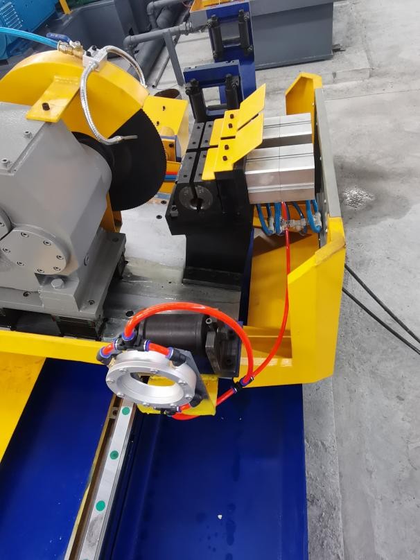
When engineering inline solutions, SANSO configures high-frequency tube mills to support electromagnetic inspection units immediately following the sizing stand. This positioning ensures that any weld defects or dimensional inconsistencies are captured prior to the cutting phase.
Implementing Eddy Current Testing of Tubes requires selecting the correct sensor configuration based on the tube manufacturing process and target defect specifications. The industry utilizes three primary coil arrangements:
Encircling coils completely surround the outer circumference of the tube. As the tube moves axially through the coil assembly, the entire circumference is inspected simultaneously. This configuration is highly efficient for detecting longitudinal cracks, transverse cracks, pinholes, and general raw material defects. However, encircling coils are sensitive to vibration and require precise guiding mechanisms to prevent lift-off variations from skewing the inspection data.
Unlike encircling coils, sector coils cover only a portion of the tube perimeter. In welded tube production, sector coils are positioned directly over the longitudinal weld seam. This focused scanning configuration optimizes the signal-to-noise ratio by ignoring the stable base metal and concentrating electromagnetic energy on the heat-affected zone (HAZ). This targeted inspection is beneficial for detecting weld-specific flaws like cold welds, stitching, and localized porosity.
Pencil probes scan localized areas and are typically mounted on rotating heads for high-precision finishing lines or used in manual verification stations. In high-speed inline tube production, rotating probe systems are sometimes implemented after the sizing section to provide helical scan paths, offering high resolution for surface micro-cracks.
In addition to physical geometry, the electrical connection of the coils determines the detection characteristics. The primary modes of operation include:
Absolute Mode: Utilizes a single detection coil to measure absolute changes in electromagnetic properties. This mode is suitable for detecting gradual variations, such as wall thickness changes or slow alloy drift.
Differential Mode: Employs two adjacent coils wound in opposition. As the tube passes, the system compares the signal from one coil to the other. Since gradual changes affect both coils simultaneously, the differential mode ignores them, focusing instead on sudden, localized discontinuities like cracks or pinholes.
Implementing reliable inline Eddy Current Testing of Tubes involves addressing several material-related variables that can interfere with signal clarity. Carbon steel and other ferromagnetic materials present a major challenge due to high and variable magnetic permeability.
Localized variations in permeability generate significant background noise, masking actual material defects. To resolve this issue, inspection systems incorporate magnetic saturation yokes. These yokes subject the tube to a powerful direct-current (DC) magnetic field prior to passing through the test coils. Saturating the material magnetically reduces its relative permeability to near unity, making the ferromagnetic tube behave magnetically like a non-ferrous material (such as stainless steel or copper). This eliminates permeability noise, allowing the testing system to detect structural discontinuities clearly.
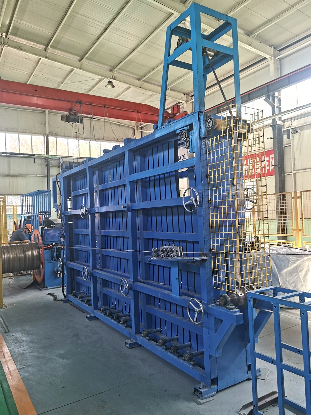
Another major obstacle on the factory floor is mechanical vibration. As the tube travels from the welding section through the sizing stands, mechanical misalignments can cause the tube to bounce or shift within the test coil. This shifting, known as lift-off, alters the distance between the coil and the tube surface, generating false alarm signals. Industrial line configurations designed by SANSO address this by using heavy-duty guide roll assemblies and non-magnetic stabilizing sleeves to keep the tube centered through the inspection zone.
Additionally, the heat-affected zone (HAZ) of the weld often exhibits different electrical and magnetic properties compared to the parent metal due to localized thermal cycling. If testing occurs immediately after welding without proper cooling, thermal variations can distort the electromagnetic signals. Water cooling jackets and precise positioning downstream are necessary to allow the tube temperature to stabilize before it enters the testing field.
To ensure compliance with international quality standards such as ASTM E309, ASTM E426, and ISO 10893-2, calibration procedures must be executed regularly. Calibration involves passing a reference standard tube containing artificial defects through the inspection system.
Common artificial calibration standards include:
Drilled Holes: Flat-bottom or through-wall holes drilled at specified diameters to define amplitude thresholds for localized material loss.
Longitudinal and Transverse Notches: Precise electro-discharge machined (EDM) notches placed on both the internal and external surfaces to establish sensitivity levels for surface cracks.
The signal received by the testing equipment is displayed on an impedance plane, representing both signal amplitude and phase angle. Phase angle analysis is the primary method for distinguishing between genuine material defects and harmless variables such as lift-off or surface scale.
By adjusting the phase angle, operators can rotate the signal display so that lift-off noise occurs along a horizontal axis, while true defect signals project vertically. This phase discrimination prevents false rejects and ensures that only tubes with structural voids, cracks, or weld discontinuities are flagged for rejection.

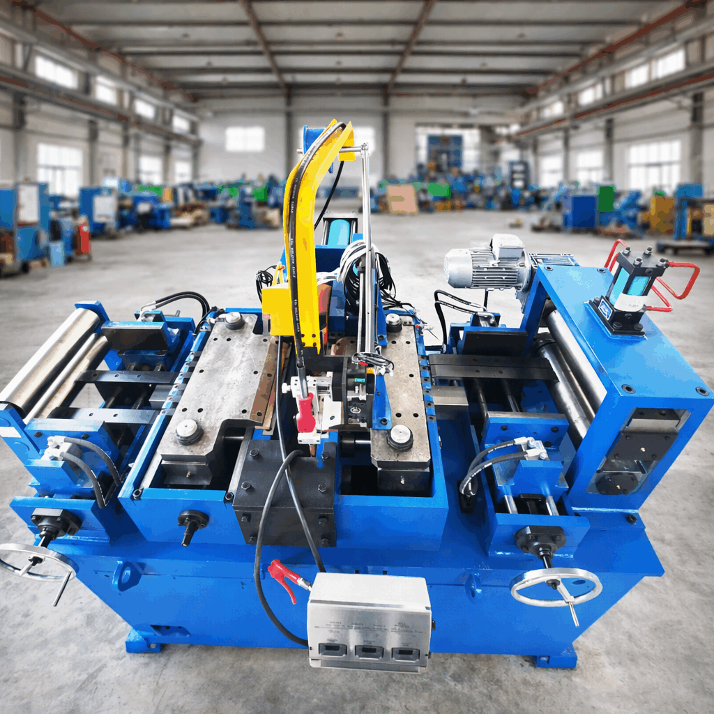
Integrating Eddy Current Testing of Tubes into a continuous mill requires coordination between the mechanical tube former, the welding station, and the NDT instrumentation. The inspection unit is typically installed after the sizing section, where the final outer diameter and ovality of the tube are established.
Modern tube manufacturing lines utilize automated marking and sorting systems. When the inspection unit detects a signal that exceeds the pre-set threshold, it sends a high-speed signal to a PLC (Programmable Logic Controller). The PLC tracks the position of the defect as the tube moves forward, activating an automatic paint sprayer to mark the exact location of the flaw. Once the tube is cut to length by the flying saw, a sorting gate automatically diverts the marked tube to a separate reject pocket.
For high-capacity manufacturing operations, SANSO integrates structural mechanical frames, precise guide rolls, and automated marking systems directly into their tube production lines. This structured setup guarantees that testing equipment functions under stable physical conditions, reducing false reject rates and maximizing line throughput.
Q1: What materials can be inspected using eddy current testing?
A1: This testing method is suitable for all electrically conductive metals. This includes non-ferrous materials such as copper, brass, aluminum, and austenitic stainless steels, as well as ferrous materials like carbon steels, provided that a magnetic saturation system is used to suppress magnetic permeability variations.
Q2: Can eddy current testing detect defects on both the inside and outside of a tube?
A2: Yes, but the ability to detect internal diameter (ID) defects depends on the tube wall thickness, material conductivity, and the excitation frequency. For thicker walls, lower testing frequencies are required to allow the electromagnetic field to penetrate to the inner surface, though this reduces overall sensitivity to small outer diameter (OD) flaws.
Q3: What is the main difference between absolute and differential coils in tube testing?
A3: Absolute coils measure the total electromagnetic properties of a single area, making them ideal for detecting gradual variations like wall thinning. Differential coils use two opposing windings to compare adjacent areas, making them highly sensitive to sudden, localized defects like pinholes and cracks while ignoring gradual dimensional drifts.
Q4: Why is magnetic saturation necessary for testing carbon steel tubes?
A4: Carbon steel is highly ferromagnetic, meaning its magnetic permeability varies widely across the material due to internal stresses and crystal structure variations. These variations cause significant electromagnetic noise that masks defects. A magnetic saturation yoke applies a strong DC magnetic field to saturate the material, reducing permeability fluctuations to near zero and allowing clean defect signal detection.
Q5: How does line speed affect the performance of eddy current testing systems?
A5: Modern systems can easily inspect tubes at speeds exceeding several hundred meters per minute. However, high speeds require high-frequency instrumentation to maintain sufficient sampling density along the tube length. Precise synchronization between the line speed, the PLC tracking system, and the marking device is necessary to accurately locate and reject defective sections.
For detailed engineering specifications regarding tube mill integration, inline inspection options, or custom manufacturing solutions, please direct inquiries to our technical support and sales team via our official communication channels:
Web Portal: https://www.sansotubemill.com/
Product Specifications: https://www.sansotubemill.com/products.html