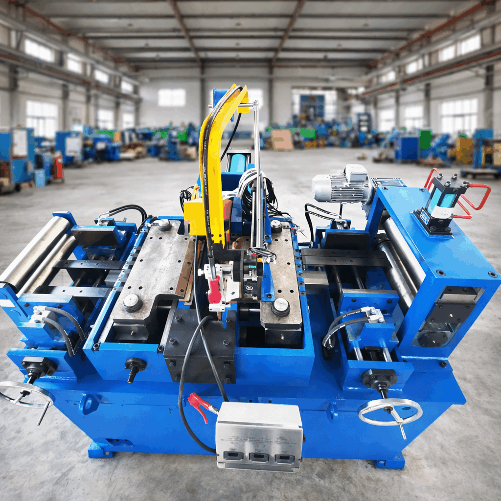
Continuous welded tube production demands rigorous quality control. The rapid speed of modern forming and welding operations requires instantaneous detection of structural anomalies. In high-performance piping sectors—ranging from automotive structural components to heat exchangers—the implementation of Eddy Current Testing of Tubes has become a standard methodology for identifying surface and near-surface imperfections. Heavy-duty manufacturing environments require machinery that seamlessly integrates these inspection mechanisms. To achieve this, machinery manufacturers like SANSO design tube mills with robust mechanical foundations that minimize vibration and optimize sensor alignment.
Implementing non-destructive testing (NDT) within a continuous manufacturing line requires a balance of electromagnetic physics, mechanical precision, and signal processing. By understanding the underlying mechanics of electromagnetic induction and how different tube materials respond to induced currents, manufacturers can significantly reduce scrap rates and maintain compliance with international structural standards.
This electromagnetic inspection method operates on the principle of electromagnetic induction. An alternating current flowing through an excitation coil generates a primary magnetic field. When this field is brought near a conductive material, such as a carbon steel or stainless steel tube, it induces localized circular electrical currents known as eddy currents. These currents generate their own secondary magnetic field, which opposes the primary field generated by the coil.
The presence of structural variations, such as localized wall thinning, pinholes, or weld seam discontinuities, disrupts the flow path of these induced currents. This disruption alters the overall electrical impedance of the coil system. By measuring these impedance variations, the testing equipment isolates defect signals from background noise.
Modern diagnostic systems display these impedance variations on a complex impedance plane, characterized by phase angle and amplitude changes. The phase angle is highly informative, as it allows operators to estimate the depth of a detected defect. Surface defects yield different phase angles compared to subsurface or internal flaws, enabling precise diagnostics during high-speed production. By setting specific threshold gates on the impedance plane, the system can automatically trigger sorting mechanisms or marking devices when an anomaly exceeds acceptable limits.
High-frequency induction (HFI) and laser welding processes operate at high speeds, which can sometimes introduce microscopic variations in the weld zone. Typical weld defects include:
Incomplete Weld Fusion: Occurs when the strip edges do not reach the proper welding temperature or are subjected to insufficient squeeze roll pressure.
Pinholes: Small gas pockets trapped during solidification, often invisible to the naked eye.
Longitudinal Cracking: Stress-induced fractures occurring along the heat-affected zone (HAZ) during the cooling phase.
Roll Marks and Mechanical Gouges: Caused by misaligned tooling elements or damaged forming rolls.
Detecting these anomalies manually is practically impossible at production speeds exceeding 50 meters per minute. Furthermore, delayed detection leads to large volumes of non-conforming material, which compromises the efficiency of the manufacturing facility. This is why automated inspection must occur immediately downstream from the weld box and sizing sections.
Selecting the appropriate coil configuration is fundamental to the performance of Eddy Current Testing of Tubes. The choice depends on the specific geometry of the tube and the suspected orientation of the defects.
Encircling Coils: These coils surround the entire circumference of the tube. They are highly effective for detecting transverse cracks, pinholes, and general wall thinning across the entire body. However, they are less sensitive to tight longitudinal defects located specifically in the weld seam.
Segment or Sector Probes: Positioned directly over the weld seam area. These focus the magnetic flux precisely on the heat-affected zone, providing superior sensitivity to longitudinal weld flaws without being influenced by the properties of the parent metal.
Frequency selection is dictated by the skin effect. The depth of penetration of eddy currents is inversely proportional to the square root of the test frequency, electrical conductivity, and magnetic permeability of the metal. For non-magnetic stainless steel, higher frequencies are typically applied to inspect thin walls with high sensitivity. Conversely, carbon steel requires lower frequencies to overcome magnetic permeability barriers, or the use of magnetic saturation units to temporarily render the material non-magnetic. This ensures the eddy currents penetrate deeply enough to inspect the inner wall surfaces.
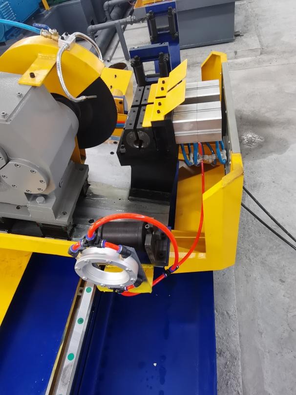
The physical environment of a tube mill is characterized by vibrations, thermal fluctuations, and the presence of cooling lubricants. These factors can introduce significant signal noise, leading to false rejects. Integrating the sensing heads requires a highly stable mechanical platform. This is why SANSO designs customized, vibration-dampened mounting fixtures located directly after the sizing stands. By maintaining a constant distance (known as lift-off) between the probe and the moving tube, the system minimizes signal drift.
Additionally, downstream demagnetization is necessary when testing ferromagnetic steels. Since the saturation yoke magnetizes the tube during inspection, an alternating current demagnetization coil must be placed immediately after the test head to restore the material's magnetic neutrality before the cutting phase. This prevents issues during subsequent cutting, chamfering, or welding operations in downstream processing.
Reliable inspection relies on proper calibration. Standards such as ASTM E309 (for ferromagnetic tubes) and ASTM E426 (for non-magnetic alloys) govern the standardized procedures for Eddy Current Testing of Tubes to guarantee quality assurance. Calibration standards are created using reference tubes of the same material, dimensions, and thermal history as the production batch.
Drilled Holes: Thru-holes of precise diameters are drilled to calibrate the system's sensitivity to volumetric defects like pinholes.
Longitudinal Notches: Electro-discharge machined (EDM) notches are placed on both the outer and inner surfaces of the reference tube to calibrate phase angle settings for depth evaluation.
Regular verification runs using these calibration standards ensure the inspection system remains within acceptable tolerance limits throughout long production shifts, providing stable and repeatable quality data.
A well-integrated inspection line does more than just reject bad material. It provides real-time feedback to the mill operator. For instance, a progressive increase in signal amplitude at a specific phase angle might indicate that the welding electrodes are wearing down, or that the forming rolls are slowly losing alignment. By identifying these trends early, operators can perform micro-adjustments before major defects occur. Industry configurations from SANSO prioritize continuous data logging, allowing quality control teams to correlate eddy current signals with specific production parameters for complete batch traceability.
Selecting and configuring the correct non-destructive testing setup requires a deep understanding of tube metallurgy, mill speed, and mechanical stability. If you are planning to upgrade your existing production line or establish a new high-speed tube mill facility, our engineering team can assist. We provide customized configurations that integrate high-performance Eddy Current Testing of Tubes into your production workflow. Contact our specialists today to discuss your specific dimensional tolerances, material specifications, and line speed requirements.
Q1: How does magnetic permeability affect the inspection of carbon steel tubes?
A1: Ferromagnetic materials like carbon steel possess high and variable magnetic permeability, which severely limits the penetration depth of eddy currents and creates massive background noise. To resolve this, a magnetic saturation yoke is utilized to temporarily saturate the material, rendering its relative permeability close to 1. This permits deeper field penetration and clear defect detection.
Q2: What is "lift-off" and how does it influence testing accuracy?
A2: Lift-off refers to the physical gap between the inspection coil and the tube surface. Variations in this distance alter the electromagnetic coupling, resulting in spurious signals that can mask actual defects. Stable mechanical guiding systems are employed to maintain a constant lift-off during high-speed tube transport.
Q3: Can this method detect defects on the inner wall of thick-walled tubes?
A3: The capability depends heavily on the skin depth equation. For thicker walls, lower testing frequencies must be applied to allow the eddy currents to penetrate to the inner surface. However, lower frequencies reduce sensitivity to small surface defects on the outer diameter. A balanced frequency strategy or multi-frequency systems are often utilized for comprehensive coverage.
Q4: How does eddy current testing compare to ultrasonic testing for welded tubes?
A4: Eddy current testing is highly suited for rapid, inline surface and near-surface inspection, particularly for detecting weld seam surface cracks and pinholes without requiring a liquid couplant. Ultrasonic testing, while suitable for detecting deep sub-surface and volumetric defects in very thick walls, typically requires water as a couplant and operates at lower line speeds.
Q5: Why is calibration with reference standards performed before every production shift?
A5: Environmental variables such as temperature drifts, coil wear, and slight changes in mill alignment can alter the system's baseline signals. Calibrating with a reference tube containing known EDM notches and drilled holes ensures the phase and amplitude settings are accurately mapped to actual defect geometries, maintaining inspection reliability.