In continuous tube and pipe production lines, the strip end joining process
directly determines overall equipment effectiveness (OEE) and final product
quality. An End Welder is not merely a supportive
device—it is the gateway to uninterrupted rolling mill operation. For plant
managers and technical directors, selecting the appropriate end welding
architecture influences scrap rates, weld seam consistency, and downstream
forming stability. This article provides a deep technical examination of modern
end welder systems, their integration with solid-state high-frequency welding
stages, and actionable solutions for common industry challenges.
1. Defining the End Welder in High-Volume Tube Mills
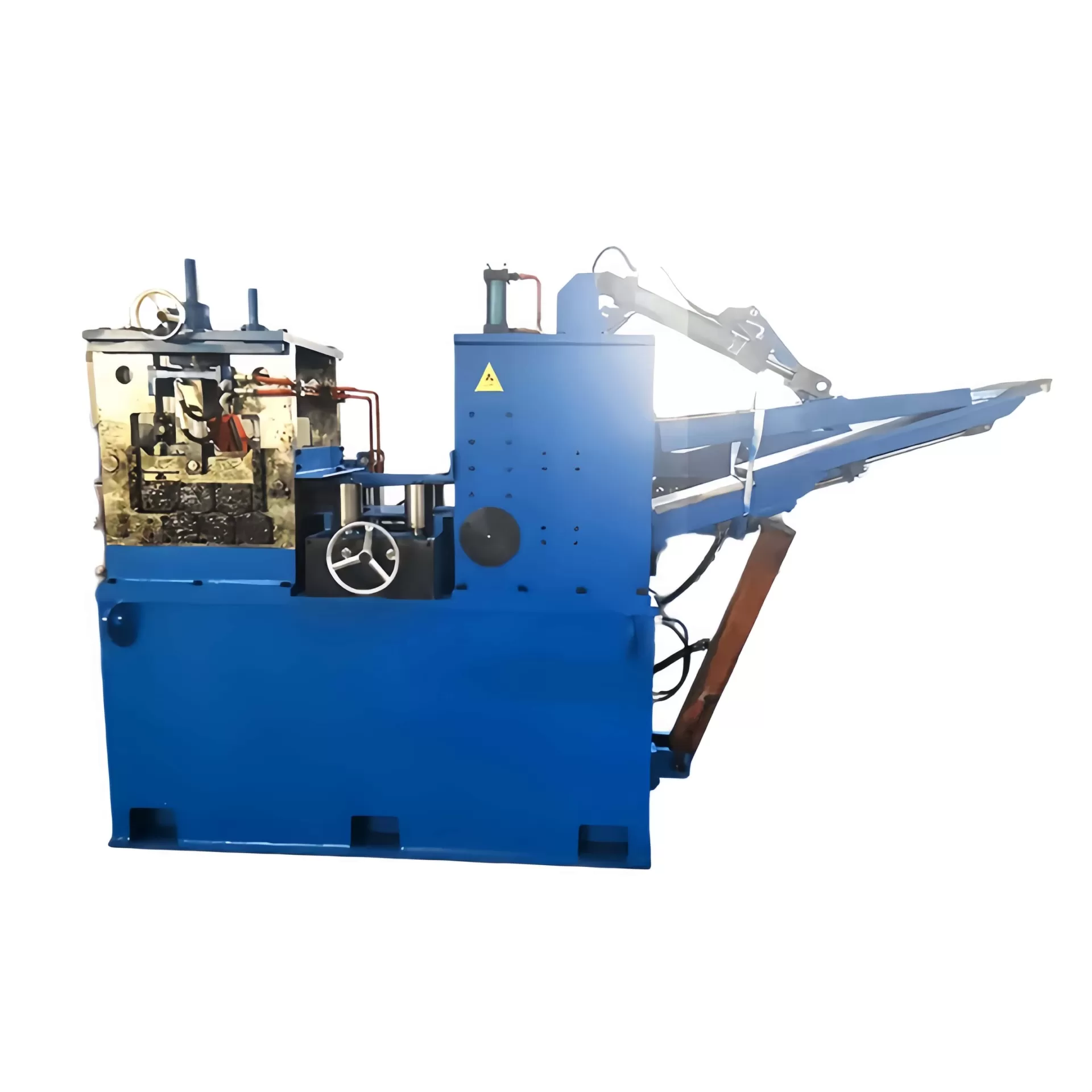
An End Welder (also referred to as a strip end welder or accumulative butt
welder) is a specialized automated station positioned before the forming section
of a tube mill. Its primary function is to join the trailing end of an exhausted
coil to the leading end of a new coil, creating a continuous strip feed. This
process prevents mill stoppages during coil changes, which is critical for
maintaining line speeds and thermal stability in the downstream
solid-state HF welder stage. Unlike roll forming or fin pass
operations, the end welder operates under strict parameters: precise edge
alignment, controlled upsetting, and minimized heat-affected zone (HAZ) to avoid
hard spots that could damage forming rolls.
In many modern lines, the same End Welder platform can process materials
from 0.8 mm to 12 mm thickness, including low-carbon steel, API 5L grades, and
austenitic stainless steels. The evolution from manual flash butt welders to
fully servo-electric or hydraulic end welders has reduced cycle times from over
90 seconds to under 25 seconds for standard strip widths, directly impacting
throughput for pipe manufacturers.
2. Core Technologies: From Clamping to Post-Weld Conditioning
A robust end welder integrates several subsystems that must operate
synchronously. These include:
Precision shearing and edge preparation: Dual-blade
cropping shears remove irregular coil ends, producing perfectly perpendicular
edges. Some designs incorporate milling heads to eliminate burrs, which improves
current distribution during flash welding.
Clamping and alignment systems: Independent hydraulic
clamps with servo-controlled backstops ensure zero gap mismatch. Alignment
sensors typically achieve an accuracy of ±0.1 mm across the strip width.
Welding head technology: Most high-performance end welders
employ a flash butt welding principle, where controlled arcing and upset force
create a forged weld without filler metal. Alternatively, solid-state HF
induction end welders are used for certain thin-wall applications.
Post-weld trimming and annealing: An integrated scarfing
unit removes internal and external flash, while localized induction annealing
restores ductility at the weld line, preventing fracture during bending through
the forming section.
Leading equipment providers like SANSO have developed end welder
configurations that communicate directly with the main mill PLC, allowing
automatic adjustments to welding parameters based on incoming coil data
(thickness, grade, width). This closed-loop control reduces operator
intervention and eliminates variability across shifts.
3. Industry Pain Points and Process-Driven Solutions
Despite advances in automation, tube manufacturers face recurring issues with
end welding. Below are four critical pain points and specific engineering
countermeasures.
3.1 Weld Breakage During Strip Accumulation or Forming
Weld failures typically occur either at the upset junction or along the HAZ,
often due to insufficient upset force or excessive heat input. A root cause
analysis frequently reveals mismatched welding parameters for the material’s
carbon equivalent (CE). Solution: Implement adaptive welding
cycles where the End Welder uses real-time resistance
monitoring to regulate flash time and upset distance. For high-strength steels,
a pre-heating stage combined with post-weld tempering through induction coils
(integrated in the same station) reduces hardness variation to less than 20
HV.
3.2 Edge Misalignment Leading to Strip Tracking Issues
Even a 0.2 mm lateral offset at the weld propagates into the roll forming
section, causing uneven pressure on one edge and potential pipe collapse.
Solution: A dual-servo centering system with laser edge
detection, coupled with wide clamping dies (≥200 mm contact length). This design
ensures the weld centerline matches the mill’s theoretical pass line. SANSO’s
end welder frames include independent side shift adjustment with digital
readouts, verifiable via a dial indicator before each weld cycle.
3.3 Excessive Downtime for Weld Parameter Changeovers
When switching between coil grades (e.g., from St52 to 304 stainless),
operators often rely on printed tables, leading to trial welds and scrap.
Solution: Recipe-based parameter storage with barcode or RFID
coil identification. Modern end welders store up to 500 weld schedules covering
material type, gauge, and mill speed. Combined with a high-speed data bus, the
End Welder can automatically retrieve the
correct parameters from the MES (Manufacturing Execution System) in under two
seconds.
3.4 Flash and Burr Damage to Forming Rolls
Residual external flash that is not fully scarfed acts as an abrasive,
rapidly wearing down tungsten carbide roll rings. Solution: Install a servo-driven scarfing tool with force feedback that follows the weld
contour after upsetting. For higher productivity lines, a two-step process:
rough scarfing while the weld is still hot, followed by a finishing pass with a
radius insert that matches the strip edge geometry.
4. Integration with Solid-State HF Welding for Seam Quality
After the end weld passes through the accumulator and enters the forming
section, the final tube seam is created by a separate solid-state high-frequency
welder. However, the condition of the end weld directly influences the
performance of that HF welder. Hard spots or excessive upset flash can disturb
the impedance matching and cause arc-outs. Therefore, leading manufacturers
design the end welder and the high-frequency induction welder as a unified
system. SANSO tube mills often pair an automatic
End Welder with a solid-state HF power source (ranging 200 kW to 1200 kW) that
shares the same HMI. Operators can monitor both weld zones from a single
console, and the system flags any abnormal end weld geometry before it reaches
the HF coil. This integration reduces reject rates attributable to end weld
defects by over 60% in documented field applications (internal performance
records).
For mills producing line pipe or boiler tubes, non-destructive testing (NDT)
stations immediately after the HF welder detect any anomalies. When an end weld
approaches, the NDT system temporarily adjusts its rejection threshold to avoid
false calls—provided the end welder produces a consistent geometry. Without a
high-repeatability end welder, the mill must either slow down or risk false
rejections of thousands of meters of good pipe.
5. Operational Best Practices for Maximizing End Welder Uptime
To achieve mean time between failures (MTBF) exceeding 1,500 operating hours,
maintenance and operational protocols must be strictly followed. Key practices
include:
Daily electrode dressing: Flash welding electrodes (copper
alloy) should be dressed every 50–80 welds to maintain consistent current
density. Use a form tool that replicates the strip contour.
Upset cylinder alignment check: Every 500 welds, verify
that the upset cylinders apply symmetrical force using load cells. Asymmetry
greater than 5% leads to bending moments on the weld joint.
Cooling system monitoring: Flash welders generate
substantial heat at the clamp contacts. Ensure deionized water flow rates remain
above 15 L/min for each electrode. Install flow switches interlocked with the
weld start circuit.
Annual calibration of weld monitoring instruments: The
displacement sensors and force transducers that control weld cycles drift over
time. Calibration should be traceable to international standards (ISO
17025).
SANSO provides certified service
engineers for annual end welder performance audits, including weld cross-section
microhardness tests and dynamic response verification of the servo-scarfing
axes.
6. Application-Specific Requirements for End Welders
Different tube product categories impose distinct demands on end welder
design. Below is a comparison based on industry segments.
Oil & Gas (API lines): Requires end welds to pass
guided bend tests and radiographic inspection. Must accommodate wall thickness
up to 16 mm and high-strength grades (X70). Welding current control with ±1%
precision is mandatory.
Structural and mechanical tubes: Focus on surface quality
to avoid mark defects. End welders should have polished clamping dies and a
scarfing blade with chip breaking geometry.
Automotive precision tubes: Very thin walls (0.8–2.0 mm).
End welders must use low-inertia upset systems to prevent buckling. A
solid-state induction end welder is sometimes preferred over flash butt to
minimize thermal distortion.
Stainless steel tubes (hygienic/chemical): Requires inert
gas shielding during the weld cycle and post-weld pickling of the scarfing zone.
The end welder design must incorporate gas purging channels in the clamp
dies.
7. Future Trends: Smart End Welding and Digital Twins
Industry 4.0 implementations are transforming end welders from standalone
stations into data-generating nodes. Using edge computing, modern systems
predict electrode wear based on welding energy (kWh per weld) and schedule
maintenance automatically. Furthermore, a digital twin of the end welding
process—simulating current density, heat dissipation, and upset dynamics—allows
engineers to pre-qualify weld parameters for new material grades without
physical trials. SANSO’s engineering team has recently integrated such a
simulation environment with their end welder control software, reducing on-site
commissioning time by 40% for complex multi-material tube mills.
Frequently Asked Questions (FAQ) About End Welder Systems
Q1: Can an End Welder handle both carbon steel and stainless steel
coils without changing mechanical parts?
A1: Yes, modern end welders
with adjustable clamping force (from 200 kN to 1200 kN) and programmable welding
cycles can switch between materials. However, you must change electrode inserts
and possibly scarfing blades to match the material’s electrical conductivity and
strength. SANSO offers quick-change electrode cassettes that reduce changeover
time to under 10 minutes.
Q2: How does an End Welder affect the final tube's weld seam quality
when using a solid-state HF welder?
A2: The end weld itself is not
part of the finished tube seam (it is later trimmed out). However, an improperly
made end weld can cause fluctuations in strip tension and geometry, leading to
seam deviations in the HF welder. A high-quality End Welder ensures that the strip passes
through the HF coil with consistent edge condition, thereby maintaining seam
integrity.
Q3: What is the typical lifespan of clamping dies and electrodes in
an End Welder?
A3: With proper cooling and regular dressing, copper
alloy electrodes last for 6,000–10,000 welds. Clamping dies (steel with carbide
inserts) can exceed 50,000 welds. Real-time wear monitoring systems can alert
operators when the electrode face has worn more than 1.5 mm.
Q4: Is a pre-heating station required before the End Welder for
heavy-gauge strips?
A4: For thicknesses above 12 mm (API grades),
pre-heating to 200–300°C reduces the required flash current and prevents
cracking. Some end welder models incorporate integrated induction pre-heating
zones before the clamp dies. Always check the specific equipment specification
for thickness limits without pre-heat.
Q5: How can we validate the quality of an end weld without
destructive testing after every splice?
A5: In-line non-destructive
methods include analyzing the welding current profile (a standard curve for
acceptable welds) and recording upset displacement versus time—anomalies
indicate weak bonds. Additionally, a pneumatic peening test can be automated: a
small punch applies a controlled impact on the weld flash; a displacement sensor
detects delamination. This is non-destructive and takes less than two
seconds.
Selecting the appropriate End Welder architecture requires evaluating line
speed, material mix, and downstream welding technology. Whether you operate a
high-speed ERW tube mill or a specialty stainless line, the integration of a
reliable strip end welder with a solid-state HF system directly impacts
first-pass yield. For a detailed technical consultation or to request
customized end welder specifications for your tube mill, contact the SANSO
engineering team today.
Send your inquiry now — include your strip width range,
material grades, and target mill speed. Our application specialists will provide
a configuration proposal within 48 hours.
Get in touch with SANSO for your End Welder
project