In high-output tube production, a minor drop in welding efficiency can cost
thousands of dollars monthly in scrap and excess power consumption. For
international welded tube mill manufacturers, the choice of high-frequency
welding technology directly impacts both operating margins and final product
quality. Standard vacuum tube welders are increasingly becoming obsolete due to
high power consumption and frequent maintenance requirements.
Modern tube production lines demand reliable, continuous, and
energy-efficient operations. Transitioning to a high-performance Solid state HF
welder has proven to be an effective strategy for manufacturers
looking to reduce scrap rates and optimize energy usage. This transition
addresses the core technical limitations of older systems while providing better
control over the heat-affected zone (HAZ).
This guide analyzes the technical advantages of solid-state high-frequency
induction welding. We will discuss system design, impedance matching, and
practical ways to optimize your tube mill line. Whether you are upgrading an
existing line or specifying a new facility, understanding these dynamics is
essential for maintaining competitive manufacturing costs.
The Core Challenge: Balancing Heat Input and Line Speed
The primary challenge in high-frequency induction welding is maintaining a
stable weld seam while line speeds fluctuate. If the heat input is too high, the
material overheats, causing spit-outs and weak joints. If the heat input is too
low, cold welds occur, resulting in structural failures during downstream
hydrostatic or flattening tests.
A reliable Solid state HF welder addresses this issue by
utilizing fast-acting control loops. Unlike older vacuum tube designs,
solid-state units adjust their power output dynamically to match changes in line
speed. This keeps the energy input per unit length of the tube consistent, which
reduces startup scrap and improves overall yield.
Furthermore, energy losses in older systems can exceed 30% of total
electrical power consumed. A modern Solid state HF welder uses
high-efficiency MOSFET or IGBT power modules. These components operate with
minimal switching losses, converting more electrical energy into useful
induction heat at the weld V-angle.
The Oversizing Paradox: A Counter-Intuitive Approach to Welder
Selection
A common misconception in tube mill procurement is that running a welder at
or near 90% of its rated capacity is the most efficient approach. While this
logic applies to some industrial machinery, high-frequency welders operate
differently. Running a system constantly at its upper limits leads to thermal
stress, which accelerates component degradation.
Opting for a slightly oversized Solid state HF welder can
actually improve long-term energy efficiency and reliability. High-frequency
power supplies exhibit lower internal resistance and better power factor metrics
when operating within a stable 70% to 80% load range. This operating margin
prevents thermal runaway in the inverter modules and reduces the load on the
cooling system.
By avoiding extreme heat cycles, internal components like capacitors and RF
transformers experience less thermal stress. This practice can extend the
operational life of the welder's inverter section by up to 40%. It also provides
the flexibility to run thicker wall profiles or alternative alloys without
needing to purchase a new power supply.
The TEM-Grid Framework for Weld Quality Optimization
To achieve consistent weld seams, operators must balance three critical
vectors. We call this approach the TEM-Grid Framework (Thermal,
Electrical, and Mechanical alignment). If any of these three vectors is
misaligned, weld quality will decrease, regardless of the power capacity of the
Solid state HF welder.
Thermal (T): Managing the temperature distribution across
the weld V-angle. The heat must be concentrated on the strip edges to prevent
wide heat-affected zones (HAZ) that weaken the tube.
Electrical (E): Optimizing the frequency and impedance
matching. This requires selecting the correct impeder size, maintaining proper
induction coil placement, and adjusting welder frequency based on material
properties.
Mechanical (M): Controlling the squeeze roll pressure,
strip edge presentation, and guide roll stability. Even a perfectly heated edge
will fail to bond if the mechanical upset force is insufficient or
misaligned.
By evaluating your tube mill using the TEM-Grid Framework, maintenance teams
can systematically diagnose defects. For instance, if a weld fail occurs, the
team can isolate whether the root cause is electrical (such as a saturated
impeder) or mechanical (such as worn squeeze roll bearings).
Deep-Dive: The Role of Impedance Matching in Power Transfer
Power transfer efficiency in induction heating depends heavily on the
relationship between the generator and the load. The load consists of the
induction coil, the impeder, and the tube itself. If there is an impedance
mismatch, a significant portion of the high-frequency energy is reflected back
to the power supply, generating excess heat instead of welding the steel.
Modern Solid state HF welder units feature automatic
matching networks. These networks adjust the output circuit's capacitance and
inductance in real time to compensate for changes in the tube's magnetic
permeability and physical dimensions. This capability is especially important
when welding non-magnetic materials, such as stainless steel or aluminum.
Using the correct impeder is also vital for efficient power transfer. The
impeder diverts the magnetic flux away from the inner surface of the tube and
concentrates it into the weld V-angle. Operating without a functional impeder,
or using a saturated one, increases power consumption and can overheat the
internal components of the welder.
Practical Tool: HF Welder Daily Parameter Optimization Checklist
To maintain consistent operation and prevent unplanned downtime, mill
operators should follow a structured daily protocol. Below is a checklist
designed to keep a Solid state HF welder operating within its
optimal parameters.
| Check Category | Target Parameter / Action | Why It Matters |
|---|
| Cooling Water System | Conductivity < 10 µS/cm; Temp: 26°C - 32°C | Prevents internal scale buildup and maintains module cooling. |
| Impeder Inspection | Check for casing wear and verify water flow rate | Prevents thermal saturation and maintains high electrical
efficiency. |
| Induction Coil Alignment | Centered over tube, 3-5mm clearance from steel strip | Ensures symmetrical heating and prevents electrical arcing. |
| Weld V-Angle Geometry | Angle between 4 and 7 degrees | Optimizes the proximity effect for concentrated heating. |
| Power Factor Monitoring | Maintain power factor > 0.95 | Reduces reactive power charges and electrical
losses. |
Downstream Integration: Removing Bottlenecks
Improving the welding speed is only beneficial if the rest of the tube mill
line can handle the increased output. High-speed welding requires reliable
downstream automation to prevent production bottlenecks. If finishing and
packaging processes cannot keep pace with the welder, operators are forced to
run the line slower than its optimal speed.
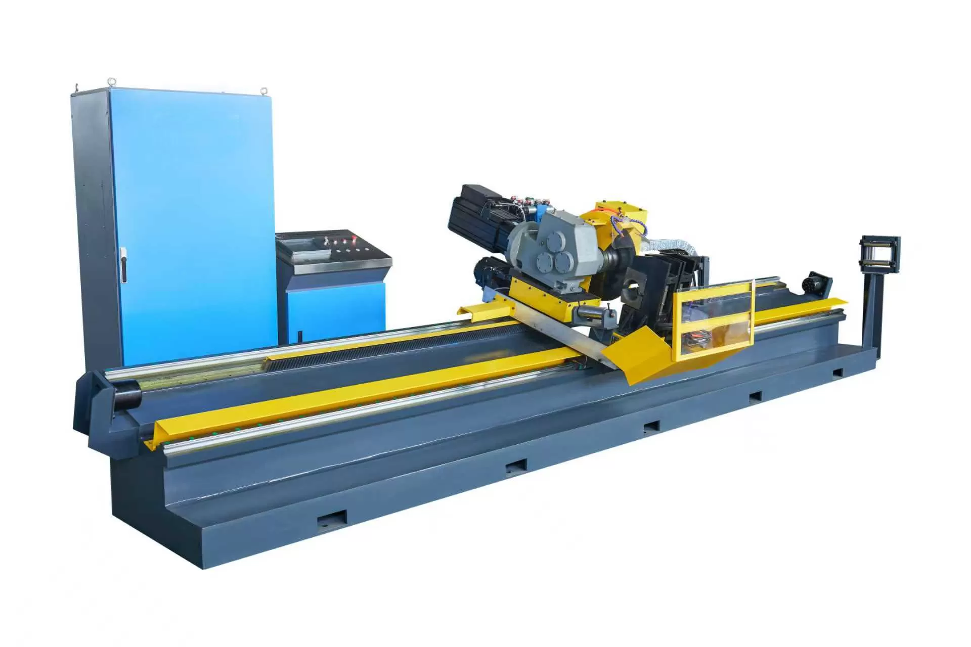
Implementing integrated downstream equipment, such as the systems
manufactured by SANSO, helps ensure that
high-efficiency welding translates directly into higher daily throughput.
Coordinating the speed of the Solid state HF welder with
automated cutting and packaging systems minimizes handling delays and protects
the finished tubes from surface damage.
A balanced tube mill line lowers operational overhead by reducing manual
handling and labor requirements. When selecting equipment, analyzing how the
welding speed aligns with the cutoff and stacking capacities is a key step in
maximizing return on investment.
Answering Common Technical Doubts
When upgrading or maintaining high-frequency welding systems, technical teams
often raise questions regarding cost, materials, and system configuration. Below
we address three common concerns in the industry.
Doubt 1: Is vacuum tube to solid-state migration worth the high capital
expenditure?
Yes. Although the initial investment is significant, the payback period
typically ranges from 12 to 18 months, depending on local electricity rates. A
Solid state HF welder typically operates with an electrical
efficiency of over 85%, compared to 50% to 60% for vacuum tube systems. This
upgrade also eliminates the high cost of replacement vacuum tubes, which are
wear-and-tear items.
Doubt 2: How do we handle impedance matching when wall thickness varies
frequently?
Modern solid-state systems use variable-frequency matching networks. When the
wall thickness or material type changes, the system adjusts the frequency and
capacitance automatically. This maintains high power transfer efficiency without
requiring manual adjustment of the internal components, which reduces changeover
times.
Doubt 3: Does switching to high frequency welding affect the metallurgical
properties of HSLA steels?
High-frequency induction welding is well-suited for High-Strength Low-Alloy
(HSLA) steels. Because the heat is highly localized, the duration of exposure to
high temperatures is very short. This produces a narrow heat-affected zone
(HAZ), which helps preserve the mechanical strength and toughness of the parent
metal along the seam.
Frequently Asked Questions
Q1: What is the main difference between MOSFET and IGBT solid state
HF welders?
A1: MOSFET-based welders are typically used for high-frequency applications
(up to 400 kHz or higher) and are highly efficient for thin-walled tubes.
IGBT-based systems are generally preferred for lower frequencies and higher
power outputs, making them suitable for heavy-duty, thick-walled pipe
manufacturing.
Q2: How does the impeder affect the efficiency of a solid state HF
welder?
A2: The impeder increases the inductive impedance of the tube's inner
surface, forcing the high-frequency current to flow through the V-angle edges
rather than around the back of the tube. This concentrates the heat where it is
needed, reducing the power required to make a weld.
Q3: What causes arc-over during the HF welding process?
A3: Arc-over is typically caused by poor coil insulation, metal slivers or
scale accumulating between the coil and the tube, or an improperly positioned
induction coil. Maintaining a clean work area and verifying coil clearance
during daily checks helps prevent this issue.
Q4: How often should the cooling water system of the welder be
serviced?
A4: Water quality should be monitored daily using conductivity meters. The
deionizing cartridges and water filters should be replaced according to the
manufacturer's maintenance schedule or when water conductivity exceeds 10 µS/cm.
The heat exchangers should be cleaned annually to prevent scale buildup.
Q5: Can a solid state HF welder be retrofitted onto an older vacuum
tube mill line?
A5: Yes, retrofitting is a common practice. The upgrade involves replacing
the old vacuum tube power cabinet and output transformer with a modern
solid-state power supply and matching system. The existing mechanical forming
sections and run-out tables can typically be retained.
Summary of Implementation Steps
Improving tube mill productivity requires a systematic approach to both
welding technology and downstream processing. Upgrading to a Solid state
HF welder reduces energy costs and improves weld consistency. By
combining modern induction heating with robust finishing systems from
experienced manufacturers like SANSO, pipe producers can
achieve reliable, long-term operational performance.