The industrial pipe rolling mill represents the convergence
of mechanical forming, high-frequency welding, and precision sizing. Whether
producing structural hollow sections, line pipe for hydrocarbons, or mechanical
tubing, the configuration of a pipe rolling mill directly
influences wall thickness consistency, weld integrity, and production uptime.
This article examines the mechanical architecture of modern tube mills, focusing
on roll pass design, strip edge preparation, weld zone stabilization, and
post-weld sizing. For plant engineers and production managers, understanding the
interplay between forming forces and material springback is the first step
toward reducing reject rates and achieving tighter geometric tolerances.
Fundamental Components of a High-Performance Pipe Rolling Mill
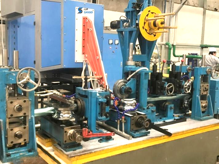
A fully integrated pipe rolling mill consists of
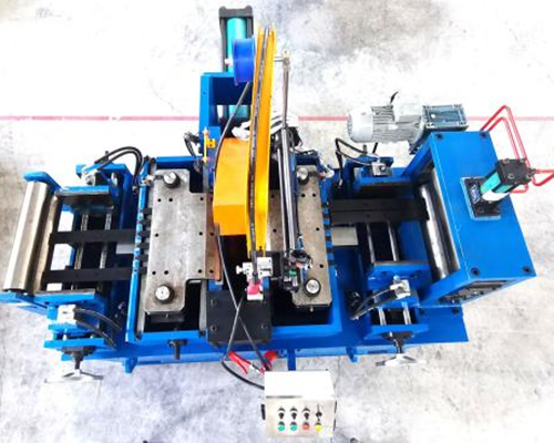
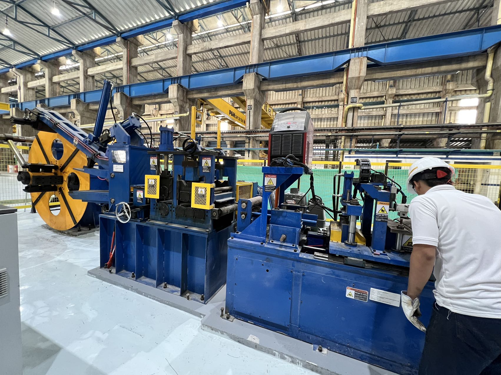
interdependent stations: uncoiler, strip straightener, shear/welder for coil
joining, accumulator, forming section (breakdown, cluster, fin-pass rolls),
welding box with scarfing tools, sizing section, straightening unit, flying
cut-off, and runout table. Each component must maintain alignment within 0.05 mm
over the entire 40-meter line. Below are the subsystems that define output
quality in a pipe rolling mill:
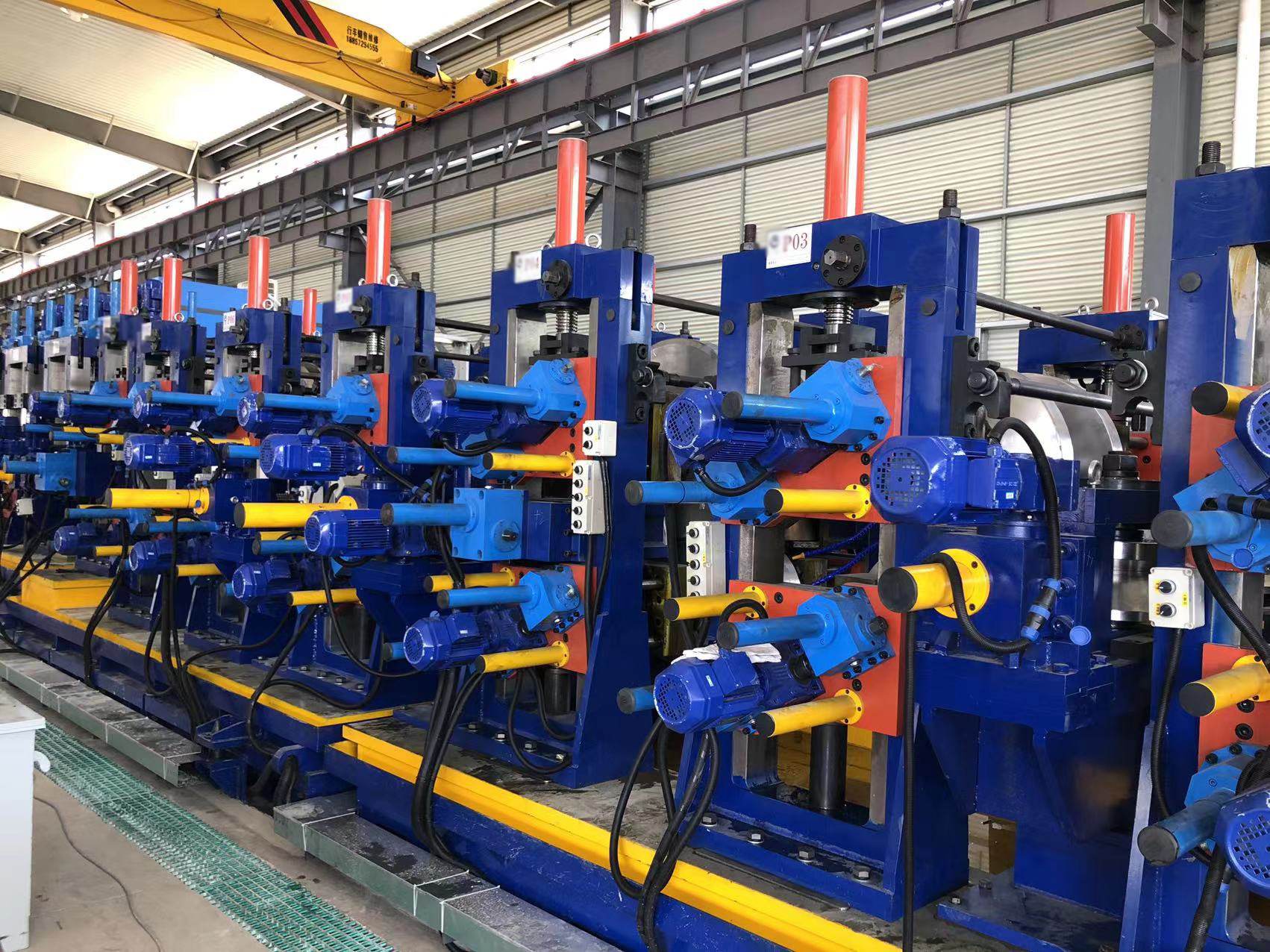
Breakdown roll stands: Initial forming passes with
increasing bend angles (from flat strip to open seam). Cage roll sets and turks
head elements control strip edge tracking.
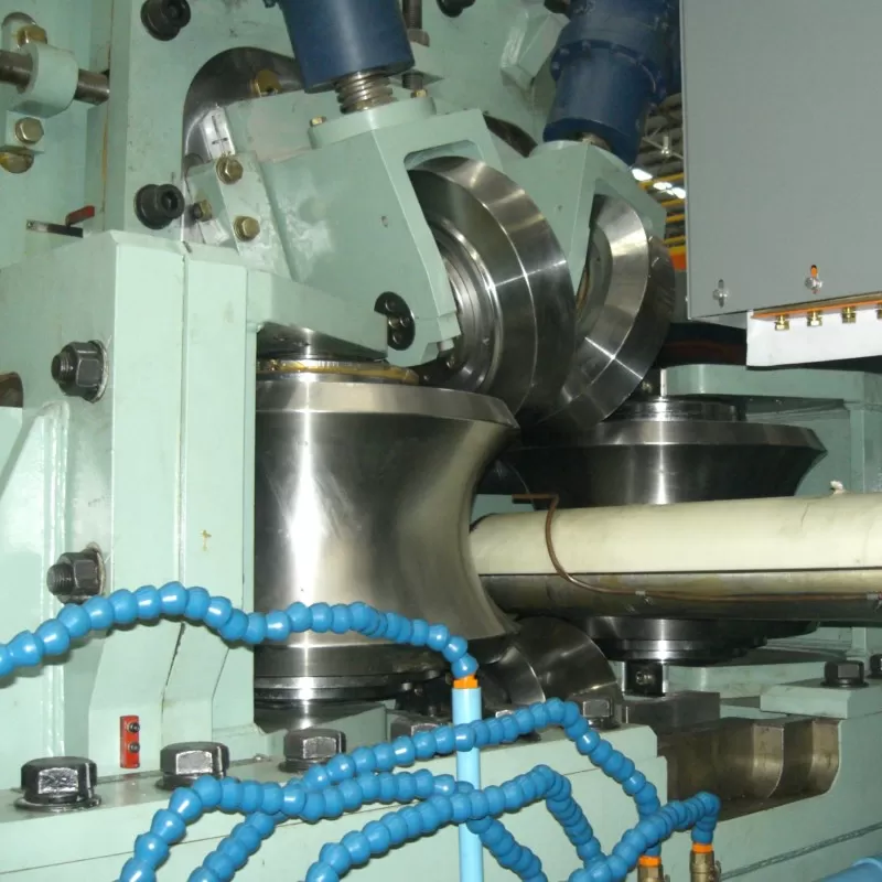
Fin-pass cluster: Close-gap rolls that bring strip edges
into parallel alignment for welding. Precise gap control prevents edge mismatch
(high-low defect).
High-frequency induction welder: Solid-state power source
(200–600 kHz) with impedance and magnetic real-time adjusters. Weld V-angle and
heat input directly affect grain structure in the heat-affected zone.
Sizing block (multi-stand): Reduces outer diameter after
welding, eliminates ovality, and imparts final straightness. Each stand includes
top, bottom, and side rolls with independent screwdowns.
Accumulator loop: Horizontal or vertical configuration that
decouples strip feeding from the high-speed forming process. Essential for
continuous operation during coil splicing.
For heavy-wall pipe (≥6 mm thickness) or high-strength materials (yield
strength > 450 MPa), the pipe rolling mill must incorporate
additional roll stands with larger shaft diameters (≥150 mm) to resist bending
deflection. Without such rigidity, the forming force causes roll gap spreading,
producing tapered walls — a common cause of downstream leak failures during
hydrostatic tests.
Addressing Persistent Industry Pain Points in Roll Forming Operations
Even well-maintained pipe production lines encounter recurring problems that
degrade final product quality. These issues are often rooted in mechanical wear,
material variability, or outdated control logic. The most frequent obstacles
observed in global pipe rolling mill operations include:
Strip edge wave (edge buckling): Caused by excess
compression in the outer arc of the formed tube. This defect leads to uneven
weld penetration and intermittent flash formation.
Weld seam offset (high-low): Misalignment of strip edges
before the welding point. Typically results from worn fin-pass rolls or improper
side guide adjustment.
Residual stress induced camber: After sizing, the pipe
curves laterally because of asymmetric cooling or unequal roll gap pressure.
Requires multi-roll straighteners with skewed adjustment.
Accumulator tension fluctuation: Sudden changes in strip
tension during accumulator charging/discharging cause strip snaking and edge
damage. Without servo-driven pinch rolls, surface scratches propagate into the
weld zone.
Roll tooling galling: Adhesive wear on roll surfaces when
forming galvanized or aluminum-killed steels. Leads to longitudinal marks on
pipe exterior and requires chromium-plated or DLC-coated rolls.
Solving these demands systematic root-cause analysis rather than reactive
adjustments. For instance, edge wave is often eliminated by reducing the initial
breakdown bend angle by 2°–3° while increasing the side roll pressure in the
cluster stands. Weld offset can be corrected by installing laser edge sensors
that feed data back to the fin-pass roll positioning screws. Many modern
pipe rolling mill lines now
integrate in-line wall thickness monitoring (ultrasonic array) that triggers
automatic screwdown compensation within 0.01 mm resolution — reducing scrap from
2.2% to below 0.7%.
Advanced Sizing and Straightening Strategies for Precise Pipe Geometry
The sizing section of a pipe rolling mill determines final
outside diameter, roundness, and straightness. Traditional two-roll
vertical/horizontal stands have evolved into multi-roller turks head designs
with independent horizontal and vertical adjustment. For high-frequency welded
pipe, the sizing block also affects weld seam microstructure by imposing light
reduction (typically 0.3%–0.8% of OD) that closes any remaining porosity. Key
parameters for sizing optimization include:
Percent reduction per stand: For carbon steel pipe (OD
60–168 mm), reductions of 0.2%–0.4% per stand over 5–6 stands produce optimal
roundness without overworking the weld.
Roll gap parallelism: Using digital level sensors, the top
and bottom rolls must maintain parallelism within 0.02 mm/m; deviation creates
spiral marking and ovality.
Straightening roller angle: Multi-roll straighteners (6–7
rolls) with crossing angles between 28° and 34° remove residual bending moment.
For thin-wall pipe (<2 mm), lower angles (22°–26°) prevent flattening.
In-line gauging: Laser micrometers positioned after the
last sizing stand provide closed-loop feedback to adjust screwdown positions,
maintaining OD tolerance of ±0.3%.
Beyond roundness, the straightening process influences weld seam fatigue
resistance. Over-straightening (excessive bending cycles) can induce
micro-cracks in the heat-affected zone. SANSO has developed straightening
units with force-limited rollers that prevent overworking — a feature
particularly valuable for API 5L X70 grade pipe where ductility is already
limited by the alloy chemistry.
Material Flow and Accumulator Integration in Continuous Pipe Rolling
Continuous operation of a pipe rolling mill requires an
accumulator that stores strip during coil splicing (typically 45–90 seconds).
Horizontal loop accumulators with carriages and pinch rolls are preferred for
heavy-gauge strips (≥4 mm) because they provide consistent back tension of
1.5–3.0 kN. However, improper tension settings cause two common defects:
Over-tension: Stretches the strip, reducing width and
creating edge thinning. Results in underfilled weld groove.
Under-tension: Allows strip to wander laterally, causing
edge waves and misalignment at the fin-pass rolls.
Modern accumulator controls incorporate laser strip centering sensors and
motor torque feedback loops. The system dynamically adjusts pinch roll pressure
and carriage speed to maintain tension within ±2% of setpoint. This not only
improves weld consistency but also extends roll tooling life by eliminating
sudden slip events. SANSO integrates such adaptive accumulator controllers into its pipe mill designs,
enabling stable processing of strip thickness variations up to 0.3 mm without
operator intervention.
Application-Specific Configurations for Pipe Rolling Mills
Different end-use segments impose distinct requirements on the pipe
rolling mill setup. Understanding these profiles helps mill owners
select appropriate tooling and monitoring systems:
Structural Square & Rectangular Pipe (EN 10219, ASTM A500)
Requires a forming section that transitions from round to final square shape
through dedicated Turk's head stands. The weld seam must be positioned at the
corner or slightly away from the corner to avoid stress concentration.
pipe rolling mill lines for
RHS often include additional straightening rolls to correct corner radius
deviation (<1.5× wall thickness).
Line Pipe for Oil & Gas (API 5L PSL2)
Mandates 100% NDT (ultrasonic or eddy current) after sizing. The mill must
incorporate a weld annealing station (induction or gas) to restore toughness.
Wall thickness eccentricity must remain below 5% of nominal value — achievable
only with rigid sizing stands and real-time feedback.
Precision Mechanical Tube (DIN 2393, EN 10305-2)
Demands internal bead removal (scarfing) accuracy of ±0.1 mm and surface
roughness Ra ≤ 1.6 µm. Pipe rolling mills serving this sector use driven
scarfing tools with carbide inserts and chip extraction vacuums.
Each configuration involves trade-offs between production speed and
precision. For example, increasing forming speed from 40 m/min to 70 m/min
reduces per-ton cost but requires more aggressive cooling and higher roll
rigidity to maintain tolerances. SANSO engineers assist clients
in balancing these parameters based on their target product portfolio.
Maintenance Protocols to Sustain Pipe Rolling Mill Accuracy
Preventive maintenance schedules for a pipe rolling mill extend beyond lubrication and roll changes. Critical actions include:
Roll shaft alignment verification: Use laser alignment
tools every 1,500 operating hours to check parallelism and perpendicularity of
each stand. Deviation >0.1 mm requires shimming or roll cartridge
replacement.
Roll contour measurement: Optical profile projectors or
contact scanners check the forming radius after every 800 tons of production.
Regrind when deviation exceeds 0.08 mm from nominal CAD profile.
Welding coil calibration: The impedance position relative
to the strip edges must be verified weekly using a dummy copper tube test. Shift
of ±1 mm changes heat distribution by 15%.
Gearbox oil analysis: Perform spectrometry and ferrography
every 2,000 hours to detect early bearing wear in the main drive
train.
Implementing these protocols increases mean time between failures (MTBF) from
400 hours to over 1,200 hours for many mill components. SANSO provides remote diagnostics
interfaces that track these metrics and alert plant personnel when thresholds
are approached.
Conclusion: Maximizing Yield from Your Pipe Rolling Mill Investment
A well-engineered pipe rolling mill transforms raw steel
strip into high-integrity welded tube with repeatable dimensions and weld
strength. Success hinges on controlling three variables: forming force
distribution (achieved through optimized roll pass design), weld heat input (via
closed-loop induction power control), and sizing pressure (through multi-stand
automatic adjustment). By addressing common pain points like edge wave, weld
offset, and tension fluctuations, mill operators can achieve scrap rates below
1.5% and dimensional acceptance above 98%.
For plant upgrades or new line integration, working with a mill builder that
understands both mechanical design and real-time process control is decisive.
SANSO offers turnkey pipe rolling
mill solutions tailored to your product mix — from structural hollows to API
line pipe.
Ready to improve your pipe production consistency? Submit your
specifications and target standards via the inquiry form. A
SANSO forming specialist will provide a detailed feasibility
analysis within three business days.
Frequently Asked Questions (FAQ) – Pipe Rolling Mill Engineering
Q1: What is the typical forming speed range for a modern pipe rolling
mill processing carbon steel strip?
A1: For wall
thicknesses from 1.5 mm to 6 mm and diameters from 20 mm to 168 mm, forming
speeds usually range between 40 m/min and 90 m/min. Thinner walls (≤2 mm) permit
speeds up to 110 m/min, while heavy-wall (>8 mm) requires 25–35 m/min to
allow sufficient heat dissipation after welding.
Q2: How can I reduce weld seam flash without over-scarfing and
damaging the base metal?
A2: Use a closed-loop
scarfing tool with carbide insert geometry matched to the weld bead profile. Set
the tool height so it removes only 75%–85% of the external flash, then apply a
light sizing reduction (0.2% of OD) to flatten the remaining flash. This avoids
score marks that act as stress risers.
Q3: What roll material is best for stainless steel pipe rolling to
prevent galling?
A3: For austenitic stainless
(304/316), choose rolls made of D2 tool steel with chromium nitride (CrN)
physical vapor deposition coating. Coating thickness 4–6 μm, hardness 1800–2200
HV. Alternatively, tungsten carbide rolls (89% WC + cobalt binder) provide
excellent wear resistance but are more brittle and require careful handling
during roll changes.
Q4: How often should the accumulator pinch rolls be replaced in a
continuous pipe rolling mill?
A4: Replace pinch
roll rubber covers every 3,000–4,000 operating hours, or when surface hardness
drops below 70 Shore A. Steel pinch rolls (grooved or knurled) require
inspection for flat spots every 1,500 hours; replacement is necessary when
groove depth wear exceeds 0.3 mm.
Q5: Can a single pipe rolling mill produce both round and square
sections?
A5: Yes, by interchanging the forming and
sizing roll tooling sets. However, square/rectangular production requires a
turks head stand after the welding section, plus additional side straightening
rolls. Conversion time typically ranges from 6 to 12 hours depending on mill
design. SANSO offers quick-change cartridge systems that reduce
changeover to 90 minutes.
For a custom quotation or to schedule a line audit, please send your inquiry
here. Include your target pipe sizes, materials, and monthly output
requirements for a tailored proposal.