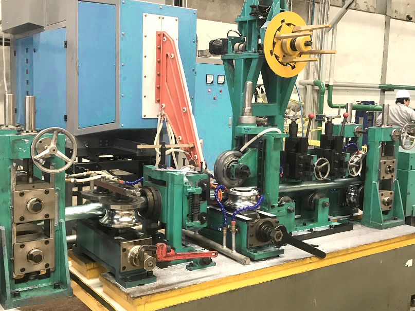
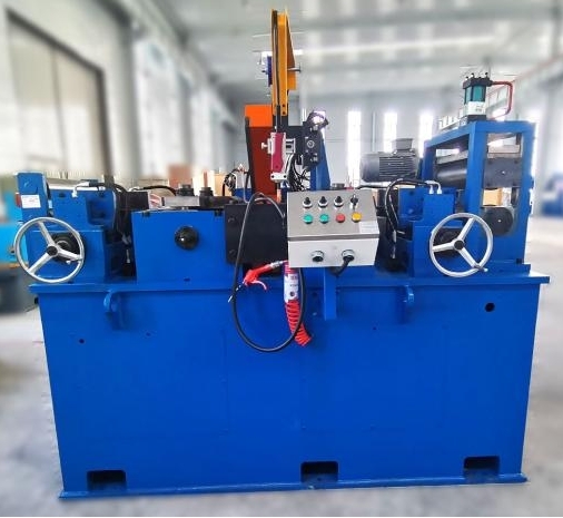
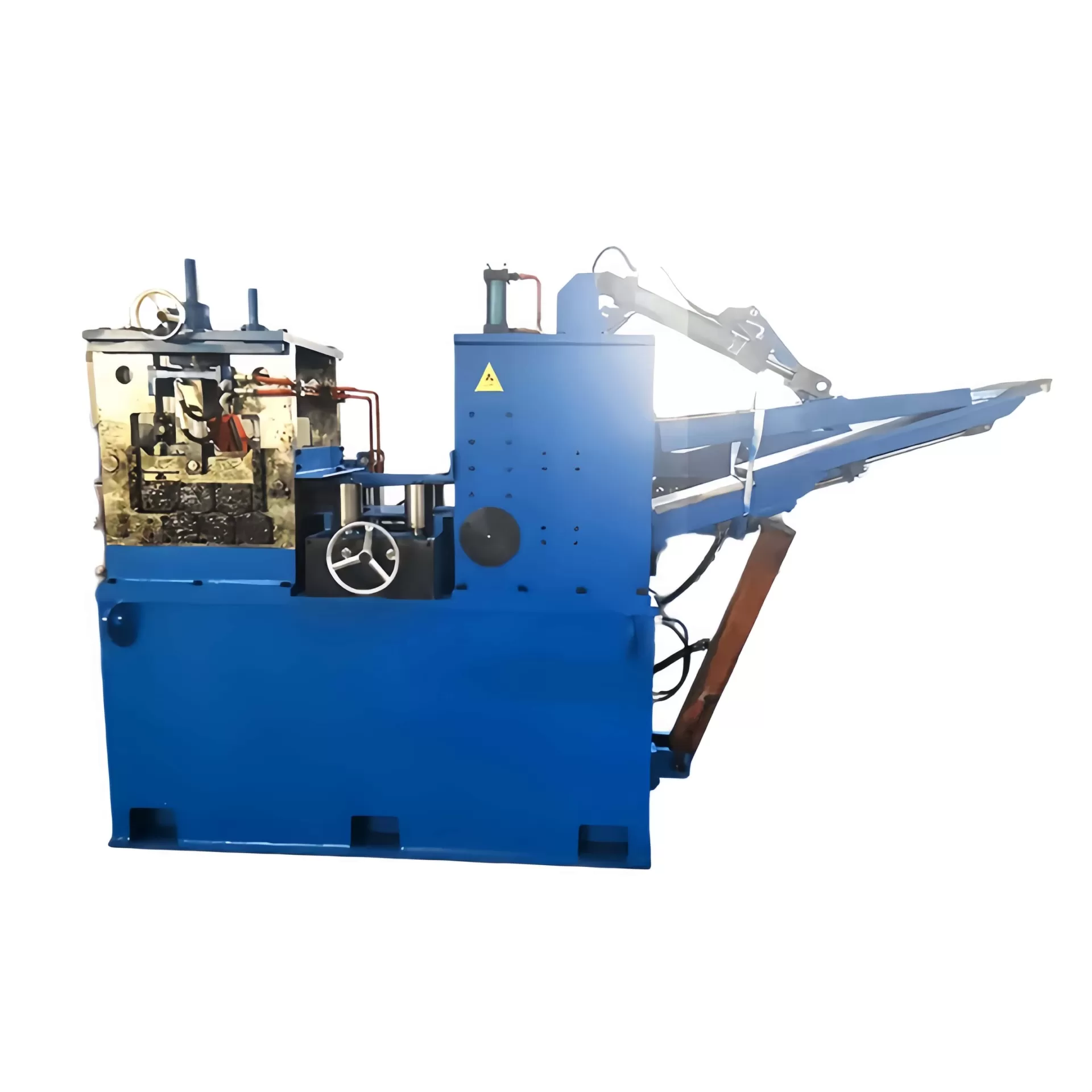
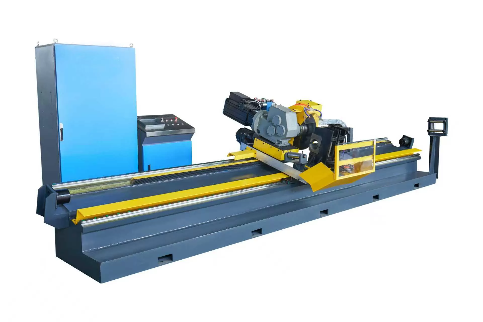
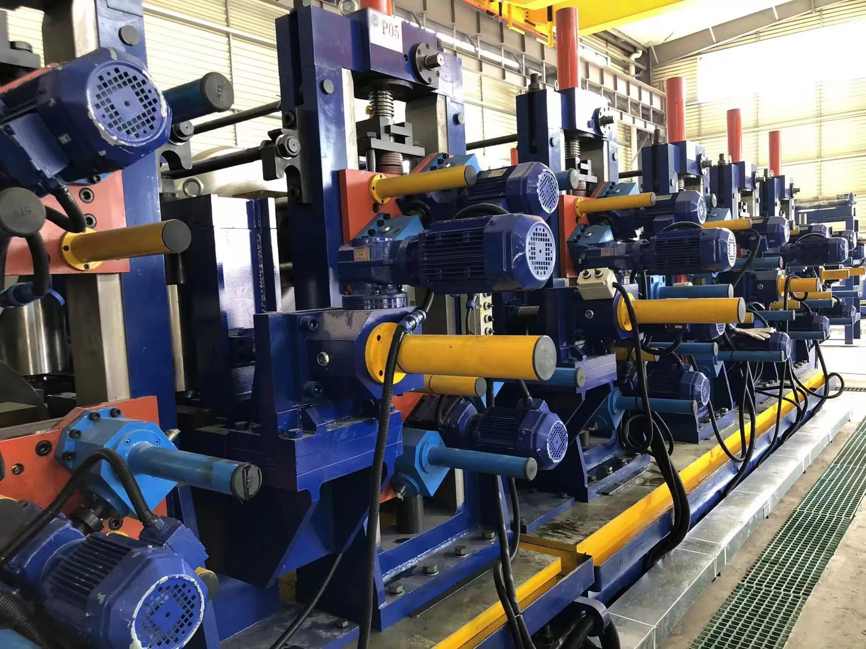
In modern tube and pipe manufacturing, achieving structural integrity at the
weld seam requires a deep understanding of induction heating dynamics. The
transition from legacy vacuum-tube oscillators to solid-state systems has
reshaped the productivity metrics of continuous roll-forming mills.
High-frequency induction welding relies on precise electromagnetic principles to
heat steel strip edges to their forging temperature before mechanical pressure
joins them. For manufacturers like SANSO, integrating a
high-performance solid
state high frequency welder into the production line is a standard
method for securing uniform weld quality and long-term mechanical
reliability.
This engineering-focused analysis explores the physical mechanisms,
electrical configurations, and operational factors that govern the performance
of high-frequency induction welding in modern industrial environments.
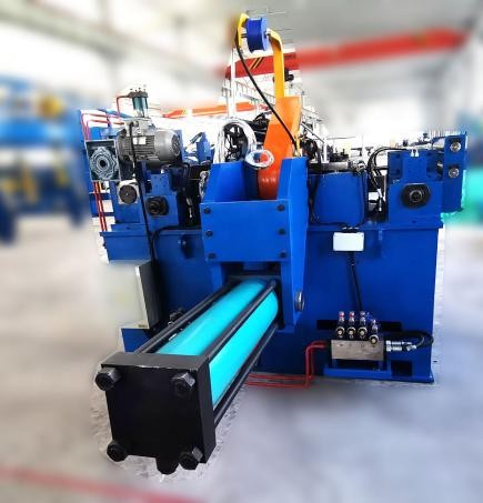
The Physics of High-Frequency Induction Welding
High-frequency induction welding operates on the principles of
electromagnetic induction, utilizing high-frequency alternating currents
(typically ranging from 150 kHz to 800 kHz) to generate localized heat. When
this current is passed through an induction coil surrounding the formed tube, it
induces a secondary current within the metal strip. This heating process is
governed by two distinct physical phenomena: the skin effect and the proximity
effect.
The Skin Effect
Unlike direct current, which distributes evenly across a conductor,
high-frequency alternating current concentrates on the outer surface of the
material. The depth of this current penetration, known as the skin depth (δ), is
determined by the frequency of the current (f), as well as the electrical
resistivity (ρ) and magnetic permeability (μ) of the target metal. As the
operating frequency increases, the skin depth decreases, confining the heat to
an incredibly thin surface layer. This rapid heating prevents thermal energy
from dissipating into the body of the tube, preserving the metallurgical
properties of the adjacent material.
The Proximity Effect
As the formed metal strip travels toward the squeeze rolls, it forms a
V-shaped gap (the "V-angle"). The high-frequency current induced in the tube
flows along the edges of this V-gap. Due to the proximity effect, the currents
flowing in opposite directions along the two edges attract each other, further
concentrating the current density at the very tips of the joint. This localized
concentration ensures that only the face edges of the strip reach their melting
point, optimizing power consumption and producing a narrow, highly defined
heat-affected zone (HAZ).
To appreciate the efficiency of modern induction systems, one must examine
the electrical architecture that replaced the high-voltage, fragile vacuum tubes
of the past. A modern solid-state welder utilizes robust semiconductor devices
to manage high power outputs with minimal energy losses.
1. The Rectifier Unit
The system begins with the incoming three-phase AC power supply, which is
directed to a solid-state rectifier. This unit converts the AC voltage into a
controllable DC voltage. Modern configurations often utilize silicon-controlled
rectifiers (SCRs) or diode bridges paired with IGBT-based buck-boost regulators.
This setup ensures a stable, ripple-free DC output, which is a key requirement
for maintaining a constant weld bead even during fluctuations in the main grid
voltage.
2. The Inverter Bridge
The inverter bridge is the heart of the solid
state high frequency welder. It converts the rectified DC power
back into high-frequency AC power. This conversion is achieved using arrays of
Metal-Oxide-Semiconductor Field-Effect Transistors (MOSFETs) or Insulated-Gate
Bipolar Transistors (IGBTs). These solid-state components are arranged in
parallel and series configurations to handle high power demands while switching
at frequencies up to several hundred kilohertz with negligible switching
losses.
3. Matching Circuitry and the Tank Circuit
The output of the inverter must be matched to the fluctuating impedance of
the induction coil and the pipe load. This is managed by a matching transformer
and a resonant tank circuit consisting of heavy-duty capacitors and inductors.
Proper impedance matching ensures that the maximum possible electrical energy is
transferred from the power source to the metal strip, preventing reflective
power losses that can stress the inverter modules.
Resolving Key Production Bottlenecks in Tube Mills
Continuous tube manufacturing is prone to several systematic bottlenecks that
directly impact product yield. Operating a mill line with mismatched or obsolete
welding equipment often results in scrap, joint failures, and excessive
downtime. Utilizing advanced manufacturing systems from SANSO helps mitigate
these operational risks by synchronizing physical roll-forming speeds with the
thermal output of the induction system.
Erratic Weld Seams: Fluctuations in the mill speed or
inconsistent strip thickness can lead to under-welding or over-welding. Modern
solid-state welders utilize closed-loop feedback systems that automatically
adjust the power output in real-time based on the line speed, maintaining a
uniform weld quality from start-up to full production speed.
Excessive Heat-Affected Zone (HAZ): A broad HAZ weakens the
structural integrity of the tube and can cause cracking during subsequent
bending or flanging operations. By utilizing higher frequencies made possible by
modern MOSFET configurations, operators can restrict the heat strictly to the
joint faces, minimizing the width of the HAZ.
Frequent Component Failures: Older vacuum-tube welders
require high-voltage step-up transformers and are prone to arc-overs,
necessitating frequent maintenance. Solid-state designs operate at much lower,
safer voltages, reducing the frequency of electrical breakdowns and component
wear.
Key Operational Parameters for Machine Selection
When selecting a solid
state high frequency welder for a tube mill, engineers must match
the system parameters to the specific material profiles and production speeds of
their line.
Power Rating (kW)
The required power output of the welder is directly proportional to the
volume of metal that must be heated to the welding temperature per unit of time.
This is determined by the maximum wall thickness of the tube, the strip
material, and the maximum design speed of the mill. For example, welding
heavy-wall carbon steel structural tubing requires significantly more power than
thin-walled stainless steel ornamental tubing.
Frequency Selection (kHz)
Choosing the correct frequency is a balancing act between wall thickness and
heating efficiency. As a general engineering rule:
High Frequencies (400 kHz - 800 kHz): Ideal for
small-diameter, thin-walled tubing (less than 1.5 mm). The heat remains
concentrated on the immediate surface, preventing excessive heat soak.
Medium Frequencies (150 kHz - 350 kHz): Suitable for medium
to thick-walled pipes (above 2.0 mm). The deeper skin depth allows the heat to
penetrate through the entire thickness of the strip edge, ensuring a complete
forge weld across the entire joint interface.
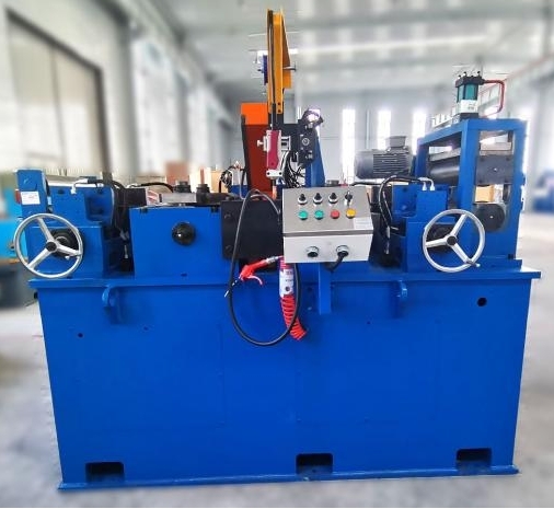
Cooling System Requirements and Maintenance
Because solid-state power devices like MOSFETs and IGBTs generate heat during
high-frequency switching, an efficient and reliable cooling system is
indispensable for preventing thermal runaway and component failure.
Most high-performance systems employ a dual-loop cooling configuration:
Internal Loop (Deionized Water): Pure deionized water
circulates through the internal copper manifolds, power modules, and matching
transformer. Deionized water is non-conductive, which prevents electrical
shorting and minimizes mineral scale buildup that could insulate the warm
components from the coolant. The electrical conductivity of this loop must be
monitored and maintained below 10 micro-siemens per centimeter.
External Loop (Industrial/Tower Water): A plate-style heat
exchanger transfers the heat from the internal deionized loop to the factory's
cooling tower or chiller water system, isolating the sensitive internal
electronics from potential environmental contaminants.
System Integration and Calibration
Proper physical alignment of the induction coil, the impeder, and the squeeze
rolls is just as important as the electrical configuration of the solid
state high frequency welder itself. The impeder, which consists of
a high-permeability ferrite core placed inside the tube directly beneath the
induction coil, serves to divert the magnetic flux away from the inner wall of
the tube and concentrate it toward the V-angle. If the impeder is positioned too
far back from the weld point, or if the coolant flow to the ferrite core is
insufficient (causing it to exceed its Curie temperature), the efficiency of the
welding process will drop drastically, resulting in a cold weld.
Collaborating with experienced mill manufacturers such as SANSO ensures that
the mechanical components, guide stands, and induction welding units are aligned
and calibrated to work in perfect synchronicity, minimizing setup times and
material waste during changeovers.
Frequently Asked Questions
Q1: What is the primary difference between a solid state welder and a
traditional vacuum tube welder?
A1: The primary difference lies in the power conversion
components. Solid-state systems use semiconductor devices like MOSFETs and IGBTs
to generate high-frequency current at lower voltages, whereas vacuum-tube
systems rely on high-voltage electronic tubes. This design difference results in
much higher electrical efficiency, improved safety, and significantly lower
maintenance requirements for solid-state systems.
Q2: Why is the position of the impeder so important during the
welding process?
A2: The impeder redirects the magnetic flux to concentrate
the induced current along the edges of the V-gap. If the impeder is poorly
positioned or loses its magnetic properties due to overheating, the current will
flow around the inside diameter of the tube instead of the edges, resulting in
high power loss and a failed weld seam.
Q3: Can a single high-frequency welder handle both carbon steel and
stainless steel?
A3: Yes, but the operational parameters must be adjusted.
Stainless steel has higher electrical resistivity and lower thermal conductivity
than carbon steel, meaning it heats up faster but requires careful control of
the weld pressure and speed to prevent oxide inclusions and ensure a clean weld
bead.
Q4: How does frequency affect the heat-affected zone (HAZ) in tube
welding?
A4: Higher frequencies concentrate the electrical current
closer to the surface of the strip edges due to the skin effect. This limits the
depth of heat penetration and minimizes the overall width of the HAZ, preserving
the structural and mechanical properties of the surrounding tube metal.
Q5: What are the water quality requirements for the internal cooling
loop of a solid-state welder?
A5: The internal loop must use high-purity, deionized water
with low electrical conductivity (typically below 10 μS/cm). Using standard tap
water or untreated water will lead to mineral scaling, corrosion of copper
components, and potential electrical short-circuits within the high-power
inverter modules.
Submit Your Inquiry for Custom Tube Mill Solutions
Optimizing a tube production line requires matching mechanical precision with
efficient induction heating systems. If you are planning to upgrade your current
welding setup or install a completely new, integrated pipe mill line, our
engineering team is available to assist you. We provide tailored configurations
designed to match your specific production requirements, wall thicknesses, and
material grades.
Contact us today to discuss your project requirements, request detailed
system specifications, or obtain a professional quote for your manufacturing
facility.