In high-speed stamping, progressive die operations, and precision roll
forming, the operational interface between raw metal coils and the primary press
tool governs downstream yield. While secondary processes such as stamping or
laser cutting receive significant focus, processing anomalies like dimensional
drift, tool wear, and feeding missteps typically originate upstream. A precisely
calibrated decoiler and straightener system is the primary
mechanism to eliminate raw material variables before strip stock contacts the
tooling.
This technical guide examines the mechanics of unwinding, plastic deformation
dynamics in roller leveling, mechanical drive configurations, and the parameters
required to match coil-processing equipment to specific manufacturing
tolerances.
1. Decoilers: The Mechanics of Industrial Strip Unwinding
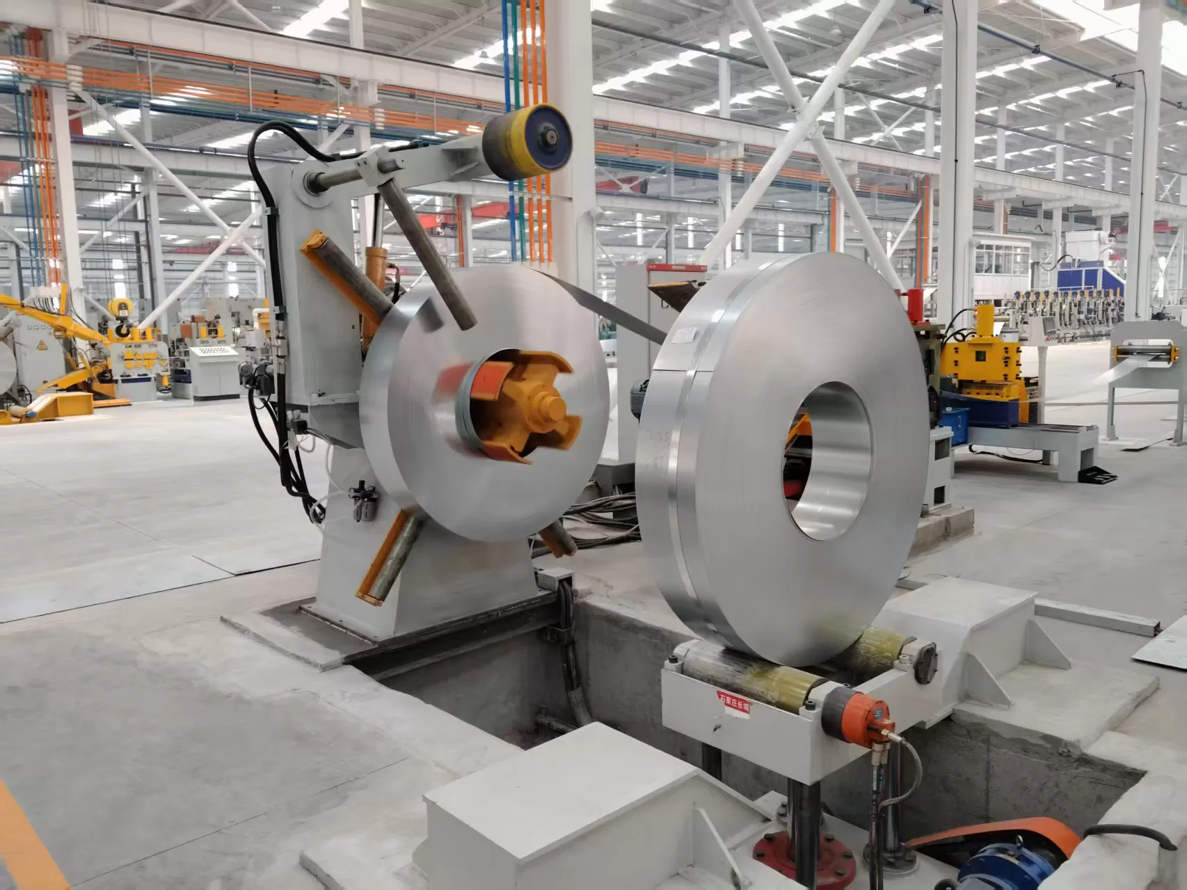
Coil processing begins at the decoiler (also known as an uncoiler). The
machine must maintain structural support for multi-ton coils while managing
variable-speed strip payoff, preventing inertia runaway, edge binding, and strip
damage.
Core Functional Components
- Expanding Mandrel: The central shaft matches the coil inner
diameter (ID). Expansion occurs via mechanical wedges for light setups or
hydraulic toggle linkages for heavy-gauge stock, preventing slippage during
rapid acceleration.
- Snubber and Hold-Down Arms: Hydraulically driven pneumatic
or urethane-coated snubber wheels exert positive outer-diameter downward force,
containing stored mechanical springback during outer-band cutting.
- Decoiler Braking Systems: Tension retention depends on
mechanical calipers, pneumatic disc brakes, or regenerative drives. Without
synchronized back-tension, inertia causes rotational overrun, loose coil wraps,
surface scuffing, and slack-loop drop.
- Loop Control Integration: Photoelectric optical sensors,
ultrasonic arrays, or mechanical dancer arms read strip position within the
accumulation loop, sending 0–10V or 4–20mA feedback to variable frequency drives
(VFD) for continuous unspooling speed regulation.
Mandrel Configurations and Structural Types
- Single-Mandrel Overhung Decoilers: Standard configuration
for coils up to 5,000 kg. Provides open-side access for crane or forklift
loading. Heavy capacities require an outboard bearing support to counter shaft
deflection.
- Double-Cone Decoilers: Used primarily for massive
heavy-gauge processing (15 to 30+ tons). Opposing motorized cones enter the coil
ID from both edges, eliminating overhung moment arms.
- Dual-Station Turnstile (Double-Head) Decoilers: Designed
for high-volume automated lines. One mandrel feeds the active straightener while
the operator loads the second spindle. A 180-degree rotation index cuts coil
changeover downtime down to minutes.
2. Strip Straightening: The Physics of Plastic Deformation
Metal winding introduces structural internal stress known as "coil set." Coil
set describes the longitudinal curvature retained by strip material after being
held at a fixed radius. Left uncorrected, coil set causes progressive-die pitch
jamming, inaccurate cut-to-length parts, and unstable strip piloting.
The Straightening Principle: Beyond Elastic Limits
Flattening metal requires more than simply bending it backwards. A
straightener subjects the strip to alternating reverse bending across offset,
staggered rollers. To eliminate mechanical memory, the outer fibers of the
material must be pulled past their yield point (elastic limit) into the plastic deformation zone.
By progressively reducing the bend radius through the entry rollers and
returning the cross-section to neutral zero-stress geometry at the exit rollers,
the material's yield stresses normalize, delivering flat, neutral stock.
Roll Geometries and Calculations
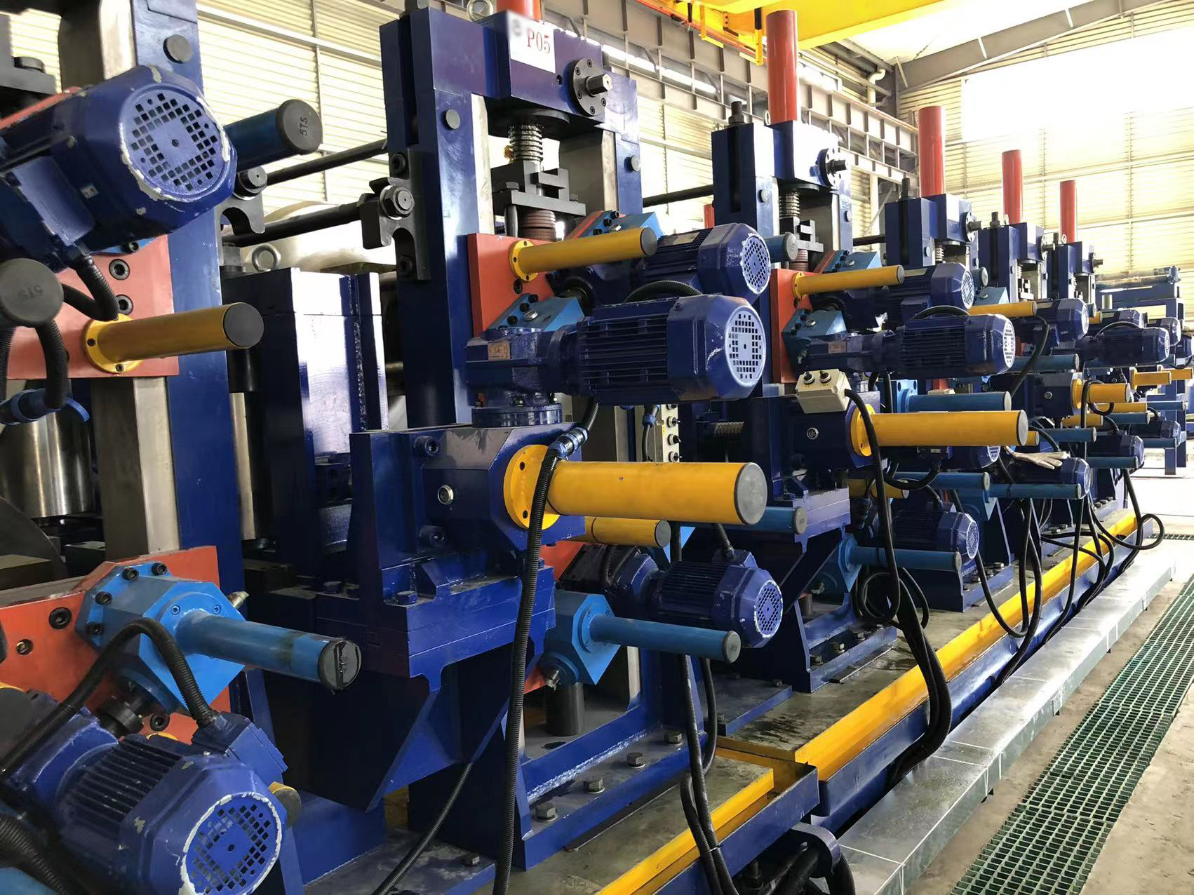
Straightener efficiency depends on roller geometry and structural
rigidity:
- Roll Diameter: Dictates minimum bending radius. Smaller
diameters correct thinner, high-yield materials; larger roll diameters resist
deflection during heavy-gauge processing.
- Roll Pitch (Center Distance): Closer center spacing
produces higher alternating deformation without requiring extreme roll
penetration depths.
- Roll Count: Standard configurations utilize 5 to 7 rolls
for basic flattening (e.g., HVAC duct, roll forming). Precision stamping
applications require 9, 11, or up to 21 staggered leveling rolls to fully
relieve residual stress and prevent crossbowing.
When selecting coil preparation machinery, production engineers must evaluate
separate machines against integrated combinations.
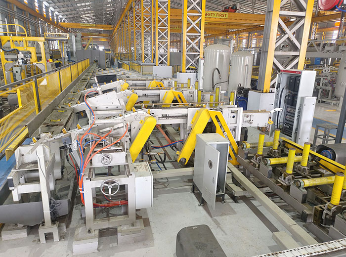
Standalone Decoiler + Straightener Lines
In a standalone architecture, the decoiler and straightener are separated by
a free-hanging accumulation pit or optical-sensor loop track. The decoiler feeds
the loop, and the straightener draws material from the slack loop.
- Advantages: The straightener runs at a steady, continuous
speed, isolating straightener pull forces from decoiler inertia.
- Disadvantages: Demands large floor space (often 8 to 15
meters in length) to maintain adequate accumulation loops without bending the
strip.
Integrated 2-in-1 Decoiler and Straightener Units
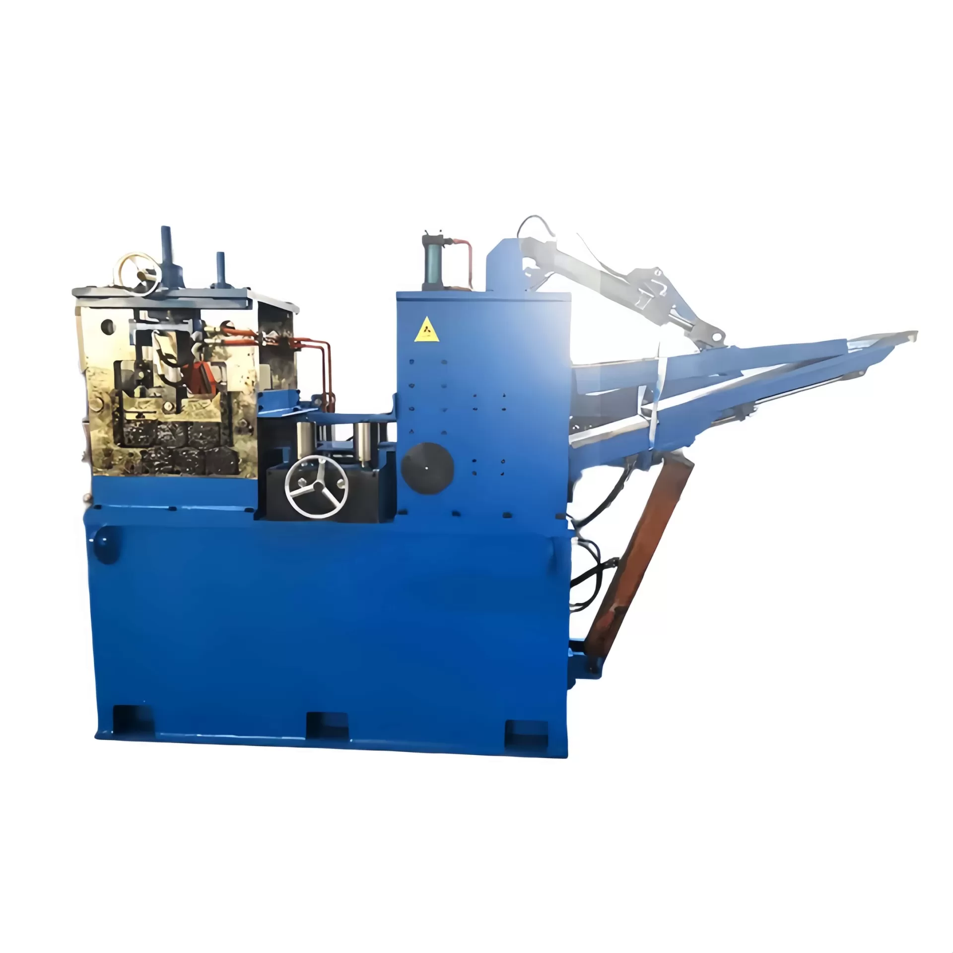
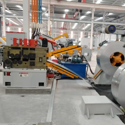
An integrated decoiler and straightener system mounts both
assemblies onto a single, heavy-duty fabricated base frame. The material
transitions directly from mandrel unspooling into the straightener pinch
rolls.
- Footprint Efficiency: Eliminates the extensive transition
pit between unwinding and leveling, cutting production floor footprints by up to
50%.
- Threading Control: Integrated hydraulic peeler tables,
pinch assemblies, and side guides route heavy-gauge coil leading edges directly
into flattening rolls without manual manipulation.
- Synchronized Drive Architecture: Common PLC-governed
controls prevent strip scuffing and slippage between decoiler release tension
and straightener intake drive speed.
4. Heavy-Gauge Coil Processing: 4mm+ Mechanics
Handling light gauge material (<2.0mm) centers around tension consistency
and surface protection. In contrast, heavy-gauge strip processing (4.0mm to
12.0mm+ structural steels) presents distinct mechanical resistance challenges
and high stored elastic energy risks.
High-Capacity Structural Elements
- Peeler Tables and De-Bending Wedges: Thick strip stock will
not bend into pinch rolls manually. Heavy-duty lines require a hydraulic peeler
blade extending toward the OD to lift the leading edge, along with a secondary
overhead breaker roll to bend the leading tip flat for roll entry.
- Hydraulic Pinch Assemblies: Entry nip pressure requires
high mechanical downforce. Heavy hydraulic cylinders drive the top pinch roller
downward to grip the leading strip without slip marks.
- Quenched and Tempered Rollers: Heavy-gauge processing
generates extreme contact stresses. Rollers are machined from tool steels such
as 42CrMo or GCr15, induction hardened to HRC 60+, chrome-plated, and precision
ground to stop roller surface grooving.
- Mechanical Back-Up Roll Support: Long, small-diameter
leveling rolls will deflect under high loads, causing uneven edge flattening.
Back-up roll flights support the central spans of work rolls, maintaining
parallel gap tolerances across the full material width.
5. Engineering Selection Matrix: Technical Sizing
To avoid selecting an undersized decoiler and straightener setup, calculate operational loads based on worst-case coil specifications
rather than nominal averages.
| Technical Parameter | Engineering Constraint | Sizing Calculation / Factor |
|---|
| Yield Strength ($\sigma_y$) | Higher yield requires deeper roller intermeshing and elevated drive power to
cross plastic thresholds. | Calculate deformation load: $P \propto (\text{Yield})^2 \times
\text{Thickness}^2$. Never specify based solely on thickness. |
| Coil Weight (Max/Min) | Overhung loading bends the main shaft, causing internal bearing distortion
and mandrel deflection. | Add a 25% safety factor for hydraulic cart shock loads. Mandrels above 5
tons require outboard supports. |
| Strip Width (Max/Min) | Roll deflection risk increases proportionally to the cube of roll
length. | Rollers require structural back-up bearings when strip widths exceed 600 mm
on high-yield materials. |
| Inner/Outer Diameter | The mandrel must expand securely without bottoming out; snubber clearance
must clear full OD limits. | Match ID expansion ranges (e.g., 470–520 mm) and confirm line elevation
matches crane heights. |
| Line Speed (m/min) | Must exceed downstream press stroke consumption without abrupt motor
start/stop cycles. | $\text{Speed} = \text{Feed Pitch} \times \text{Press SPM} \times 1.25$
(accounts for loop replenishment rate). |
6. Preventive Maintenance and Operational Reliability
Coil systems operate in heavy-wear industrial environments. Preventing
unexpected downtime requires scheduled preventive maintenance procedures.
Mechanical and Hydraulic Maintenance Points
- Mandrel Expansion Wedges: Clean and lubricate internal
sliding ramps monthly using molybdenum-disulfide grease. Grit accumulation
causes uneven wedge travel and coil slippage.
- Roll Surface Profiling: Inspect straightener rolls with
precision straight-edges quarterly. Wear grooves on the roll center reduce
leveling efficiency and damage sensitive materials.
- Hydraulic Fluid Hygiene: Maintain ISO 4406 cleanliness
levels at 18/16/13. Contaminated hydraulic fluid causes proportional valve
sticking, resulting in erratic snubber arm holding forces.
- Backlash Compensation: Check gear reducer runout, roll
universal joints, and chain drive couplings every 1,000 running hours to
eliminate intermittent feeding hesitation.
7. Advanced Coil Processing Solutions by SANSO
Engineering robust, high-performance stamping operations requires
custom-matched hardware designed for your specific material tolerances.
SANSO engineers high-durability coil automation solutions, from
high-tensile decoiler and straightener integrations to fully
automated cut-to-length processing cells.
Every SANSO system features rigid stress-relieved fabricated structures,
hardened and micro-finished alloy work rolls, and intuitive PLC-driven loop
regulation. Whether processing ultra-thin copper connectors or 12mm
high-strength automotive structural steels, SANSO lines protect tooling life and
maximize production up-time.
Contact the SANSO Engineering Team today to submit your
strip parameters, yield requirements, and stamping line targets for an expert
system layout and custom proposal.
Frequently Asked Questions (FAQ)
What is the core difference between a decoiler and an uncoiler?
While often used interchangeably in stamping operations, "decoiler" typically
denotes a powered, precision-tensioned system linked to automated feedback
loops. "Uncoiler" can describe passive, non-motorized reel cradles or
friction-braked mandrels used in less critical, pull-through operations.
Why is a straightener unable to completely correct sheet edge camber?
Standard straighteners feature cylindrical rollers that bend the material
across a single, parallel axis to eliminate longitudinal coil set. Sheet camber
results from uneven edge-to-edge material elongation created during coil
rolling. Correcting camber requires a specialized precision leveler equipped
with individually adjustable, motorized back-up roll flights that differentially
stretch localized zones across the strip.
When is a motorized decoiler required instead of a non-powered, pull-through
model?
Motorized units are required if the material is thin (preventing straightener
roll slippage and necking), heavy (where pull inertia exceeds feeder motor
ratings), surface-sensitive, or used in high-speed reciprocating press feeds
running above 40 strokes per minute.
How does coil set change from the outside of the coil to the core?
Coil set severity increases as the coil empties. The outer wraps possess a
large bend radius and low plastic strain. As the uncoiler approaches the inner
core ID, the wrap radius tightens dramatically, requiring the straightener
operator or automated PLC to progressively increase entry roller penetration
depth to maintain strip flatness.
Can one decoiler and straightener combination handle both aluminum and
high-tensile steel?
Only if the equipment is built for both material limits. Aluminum requires
larger roll diameters and urethane roll coatings to prevent work-hardening and
surface marking. High-tensile steels require smaller roll centers, back-up
roller supports, and high motor torque to cross plastic yield limits. A machine
engineered exclusively for structural carbon steel may scuff or under-correct
soft aluminum alloys.