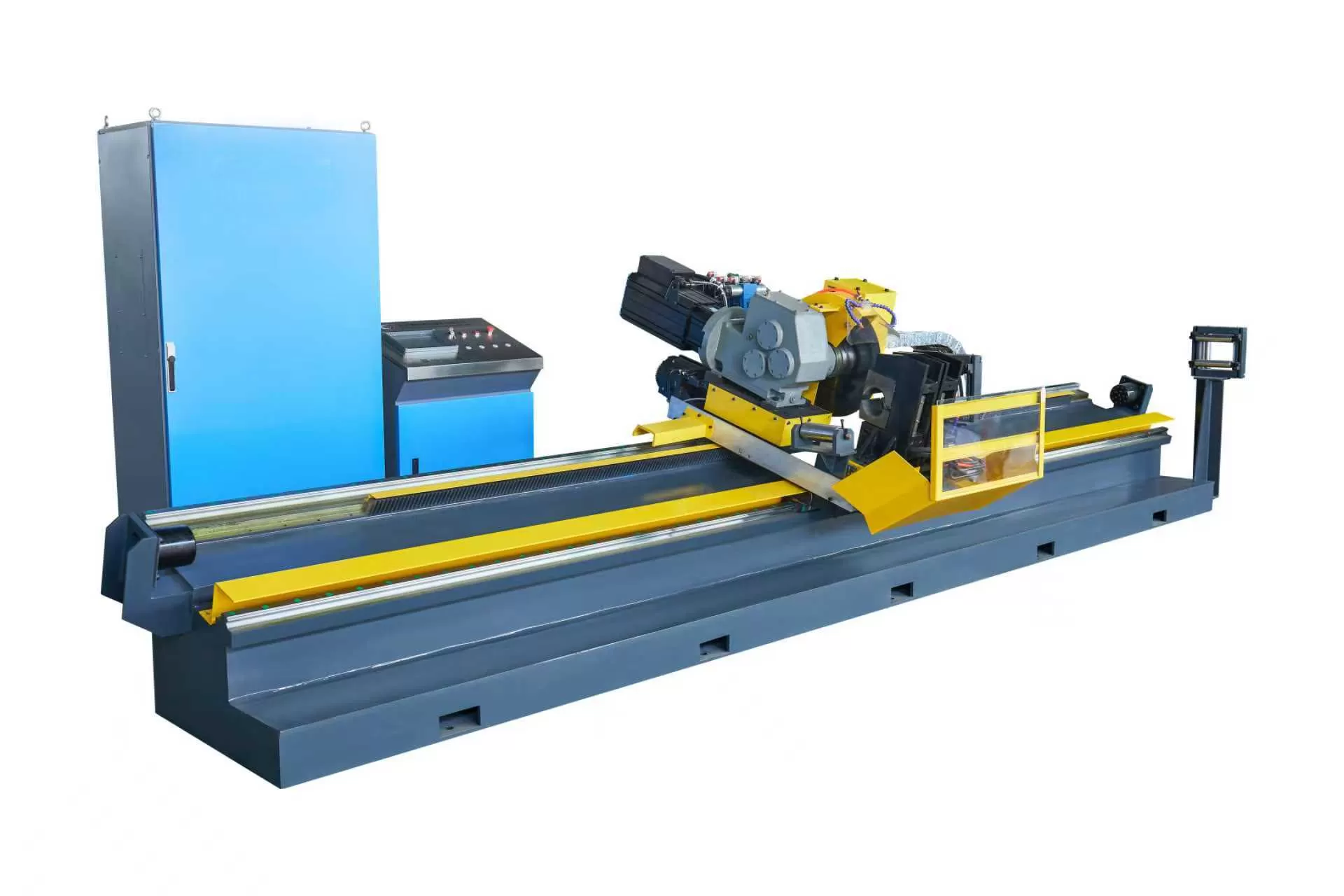
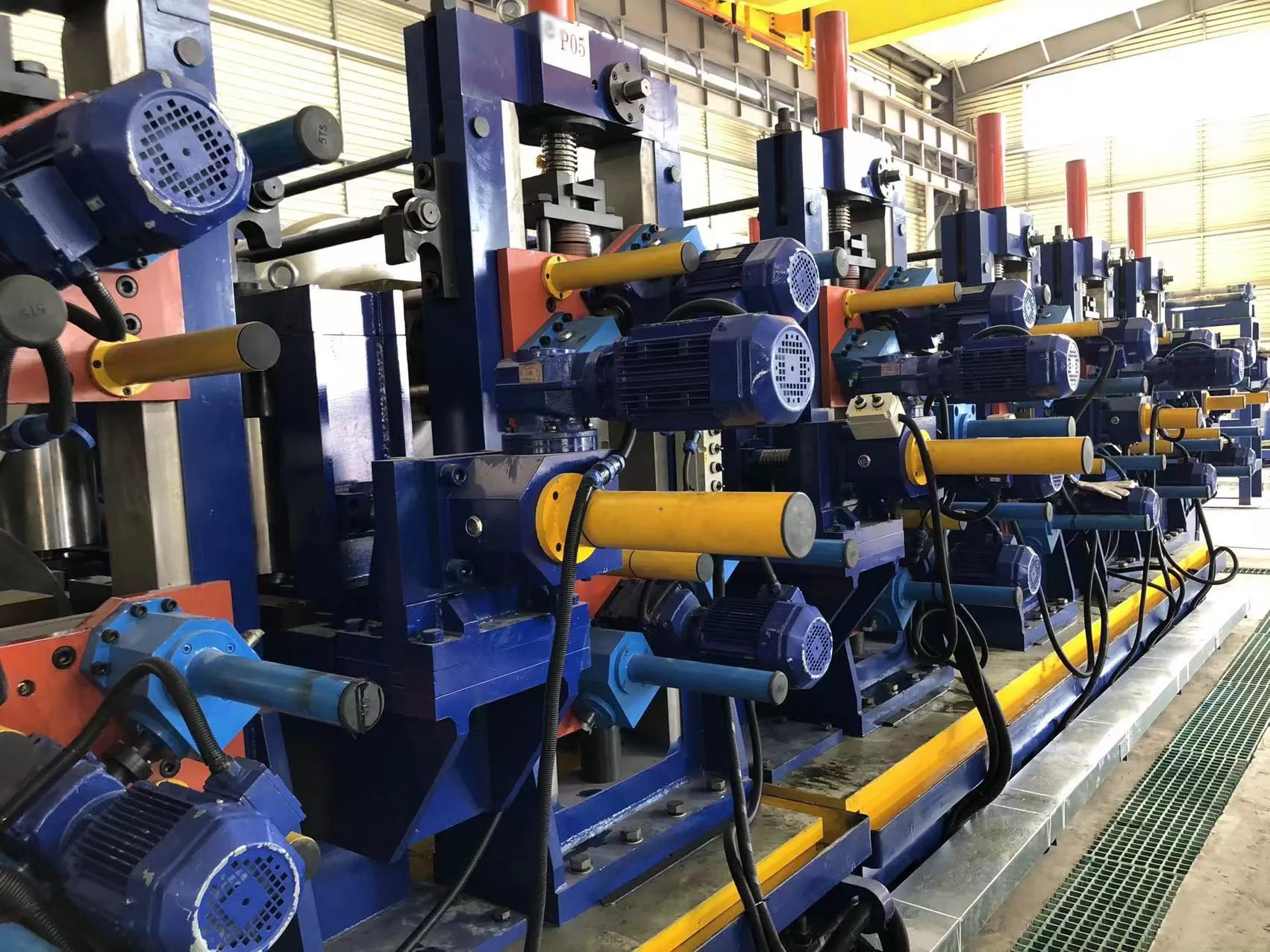
Continuous welded tube and pipe production relies on consistent raw material
behavior. Master coils delivered directly from hot or cold rolling mills contain
severe residual stresses, longitudinal curvature known as coil set, and
transverse distortions such as crossbow. Feeding raw strip directly into forming
passes without conditioning leads to edge mismatch, asymmetric high-frequency
welding seams, and premature roll wear. Combining an industrial decoiler and
straightener into the entry section of the mill stabilizes the strip before it
enters the breakdown stands, directly dictating dimensional accuracy and seam
integrity across the entire production cycle.
Mechanical Physics of Coil Distortion and Stress Relieving
Coiled strip retains mechanical memory determined by the coiling temperature,
reduction ratio, and inner-to-outer diameter ratios. When steel is wound into
tight bundles, the outer fibers undergo tensile strain while the inner fibers
experience compressive plastic deformation. As the coil unwinds, these unrelaxed
forces create irregular springback characteristics.
Correcting this condition requires cyclic reverse bending. As the strip
progresses through alternating upper and lower rolls, the material is forced
past its yield point into the plastic deformation zone. By systematically
decreasing the bending amplitude through successive roll stations, the internal
stress gradients equalize across the cross-section.
Coil Set Correction: Neutralizes longitudinal curvature
induced by coiling mandrels, ensuring the strip enters downstream processing
flat along the pass line.
Crossbow Elimination: Corrects transverse curvature caused
by uneven cooling and slit-edge stresses, preventing edge guide rubbing.
Yield Stress Normalization: Homogenizes the yield point
across the strip width, reducing uneven springback during breakdown and fin-pass
roll forming.
Architecture and Working Principles of Integrated Entry Systems
Modern tube manufacturing lines demand high rigidity and continuous feed
synchronization. An integrated decoiler and straightener must balance heavy coil
weights with micron-level positioning tolerances, managing raw strip gauges
ranging from ultra-thin precision walls to heavy structural pipe
thicknesses.
Uncoiling Mechanics and Mandrel Expansion
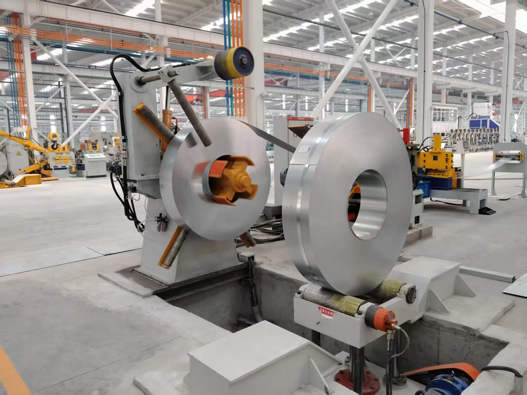
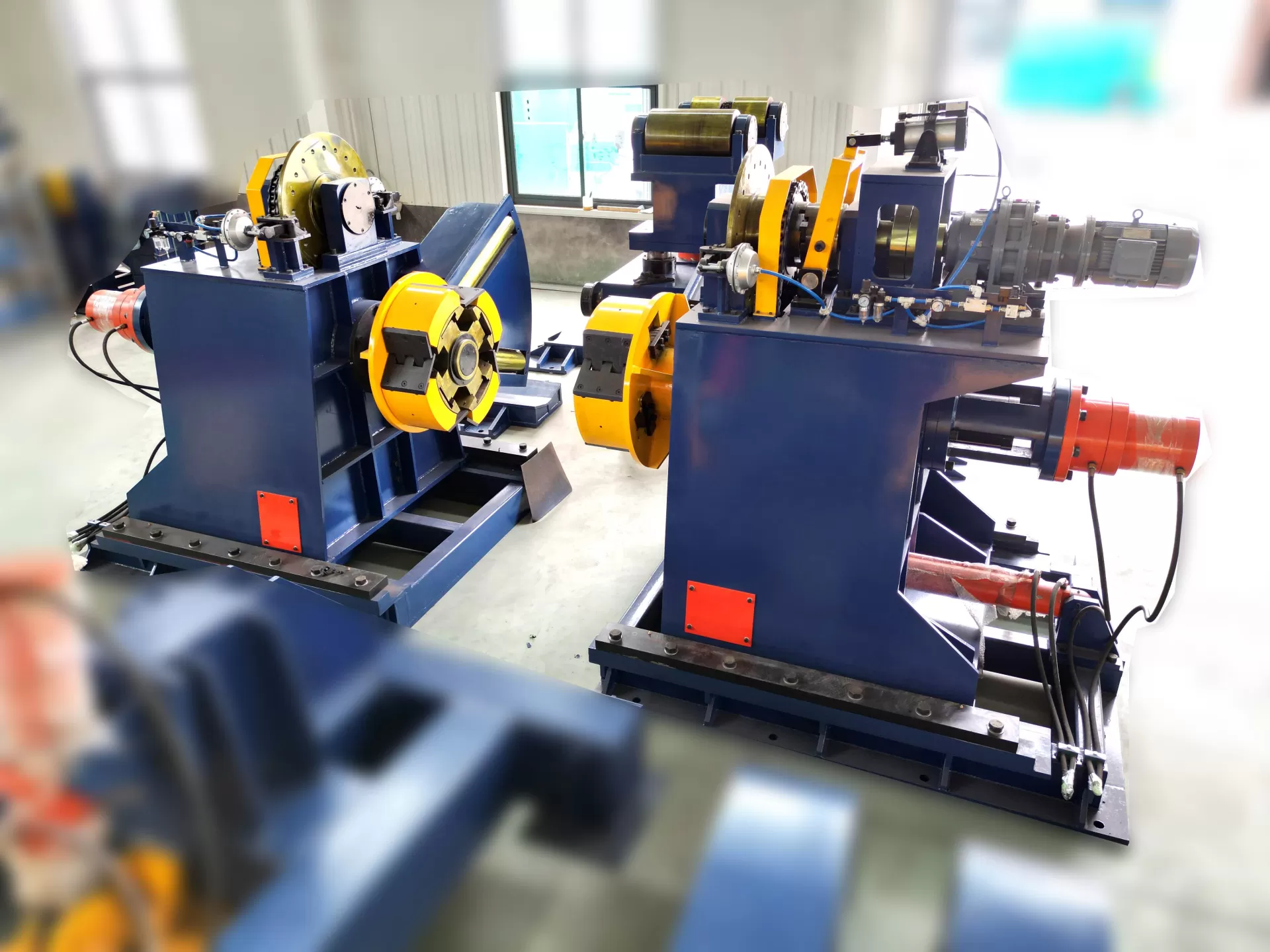
The decoiler assembly supports the master coil, maintaining continuous
centerline alignment with the tube mill axis. Expansion mechanisms typically
utilize hydraulic wedge-type or link-type segments to grip the internal coil
diameter securely without damaging inner wraps.
Back-tension control remains a primary mechanical variable. Unregulated
free-wheeling creates slack loops that induce mechanical shock loads upon mill
acceleration, while excessive tension causes strip necking and gauge thinning.
Modern systems employ pneumatic disc brakes or closed-loop AC regenerative drive
motors that adjust torque dynamically as the coil diameter decreases from outer
wrap to core.
Straightener Roll Geometry and Intermesh Dynamics
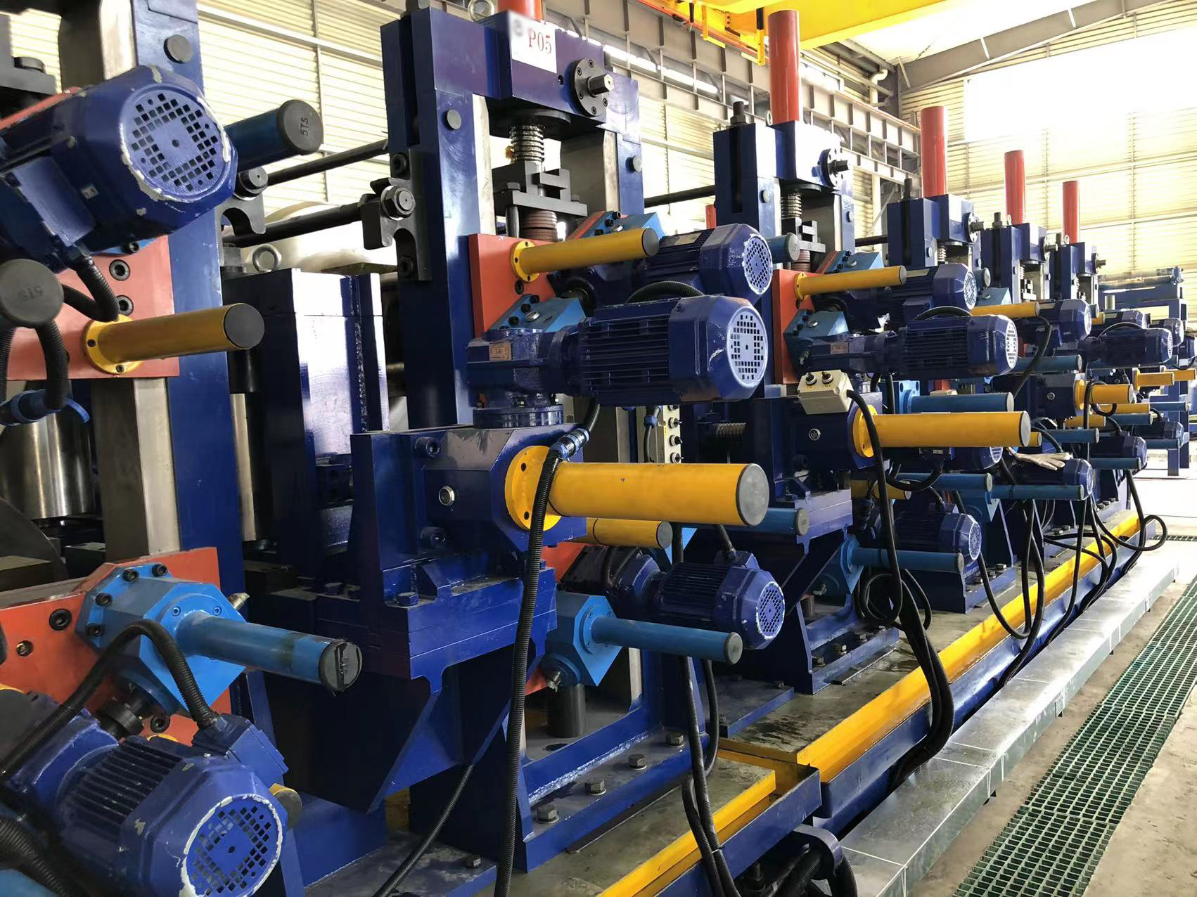
The straightener section consists of an entry pinch roll assembly followed by
a bank of staggered leveling rolls. The mechanical configuration relies on roll
diameter, roll pitch, and overall machine stiffness to achieve plastic
penetration.
Roll Configuration: Light to medium gauge processing
typically uses 7 to 11 rolls, whereas heavy-wall structural grades require
high-rigidity 5 to 7 roll layouts with increased roll centers to handle elevated
section modulus.
Work Roll Support: To prevent roll deflection under heavy
working loads, precision backup roll assemblies support the main work rolls,
preventing transverse crown variations.
Intermesh Adjustment: Entry rolls penetrate deeply into the
strip to produce maximum plastic strain (often between 70% and 80%), while the
exit rolls are positioned near the material yield threshold to deliver dead-flat
strip into the shear and end welder.
Metallurgical Considerations in Continuous Strip Leveling
Material chemistry dictates straightener setup parameters. Low-carbon
structural steels exhibit distinct yield points with high elongation, requiring
standard reverse bending profiles. High-Strength Low-Alloy (HSLA) steels and
advanced dual-phase grades exhibit high yield-to-tensile ratios and pronounced
work-hardening tendencies.
Processing high-yield materials demands precise penetration profiles. If the
roll intermesh applies insufficient strain, the strip core remains elastic,
resulting in incomplete stress relief and downstream tube twisting. Conversely,
over-straining work-hardens the strip surface, increasing forming loads in the
breakdown stands and promoting micro-cracking along the heat-affected zone
during high-frequency induction welding. Machinery engineered by SANSO addresses
these metallurgical variations by incorporating motorized roll gap regulation
with digital position feedback, allowing operators to store and recall exact
penetration parameters based on coil heat numbers and tensile properties.
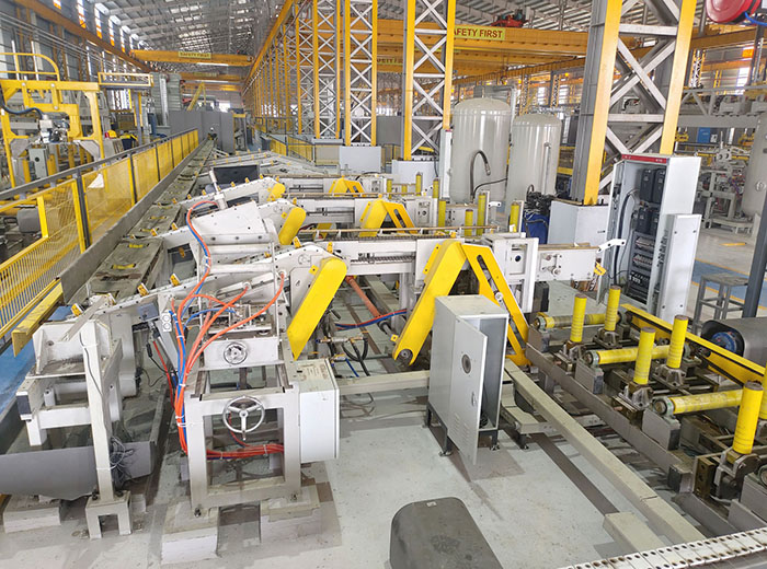
A decoiler and straightener does not operate as an isolated machine; it
functions as the lead synchronization node for the entire continuous processing
line. Smooth integration with entry loop accumulators, shear welders, and roll
forming units governs overall line efficiency.
Pass Line Alignment and Edge Guidance
Centering deviations at the entry table propagate through every breakdown
stand. Heavy-duty self-centering coil loading cars feed the decoiler mandrel,
while hydraulic side-guide rollers at the straightener exit maintain strip
tracking along the theoretical mill centerline within sub-millimeter tolerances.
This geometric consistency prevents uneven strip edge presentation at the
induction welding stage.
Loop Accumulator Feeding and Speed Coordination
Continuous tube mills require non-stop operation during coil changes. The
decoiler and straightener must accelerate to high payout speeds to refill
vertical or horizontal spiral accumulators, then decelerate safely as the coil
tail approaches the shear and end welder. Dynamic variable-frequency drives,
synchronized via central PLC networks, coordinate line acceleration curves to
prevent surface scuffing between work rolls and strip faces during speed
transitions.
| Mechanical Parameter | Thin-Wall Precision Tube Line | Heavy-Wall Structural Tube Line |
|---|
| Strip Thickness Range | 0.5 mm – 2.0 mm | 4.0 mm – 16.0 mm |
| Roll Diameter Range | 40 mm – 65 mm | 120 mm – 220 mm |
| Number of Straightening Rolls | 9 to 13 Rolls | 5 to 7 Rolls |
| Mandrel Expansion Range | 450 mm – 520 mm | 580 mm – 760 mm |
| Drive Synchronization | Dual AC Servo / Micro-Tension Control | Heavy-Duty AC Vector with Hydraulic Assist |
Mechanical Maintenance Protocols and Component Longevity
High continuous line speeds subject straightener components to severe
abrasive wear and cyclical mechanical fatigue. Establishing strict operational
maintenance routines preserves strip surface quality and prevents unscheduled
downtime.
Work Roll Surface Conditioning: Straightener work rolls are
typically fabricated from forged alloy steels such as GCr15 or 42CrMo,
heat-treated through high-frequency induction hardening to HRC 60-62, and
finished with hard chrome plating. Regular inspection for surface pitting, roll
glazing, and scale buildup prevents roll marks from transferring onto premium
pipe surfaces.
Bearing Assembly Lubrication: High-load spherical roller
bearings supporting the main drive shafts require centralized automatic grease
lubrication systems. Because entry areas generate metal scale and coolant spray,
sealing systems must prevent abrasive ingress into bearing housings.
Hydraulic Clamping and Parallelism Calibration: Over time,
mechanical wear on slide blocks and hydraulic screw-down mechanisms can cause
roll tilt. Quarterly calibration with precision dial indicators ensures upper
and lower roll shafts remain parallel across the entire working face
width.
In structural mill environments, production facilities utilize SANSO entry
processing systems engineered with rapid roll-change cassettes. This design
allows maintenance personnel to swap out complete roll banks for off-line
re-grinding and inspection without stopping mill production during tooling
changeovers.
Key Engineering Factors for Mill Line Layout Selection
Selecting the appropriate decoiler and straightener combination requires a
thorough audit of your raw material specifications, maximum coil weights, and
floor space limitations.
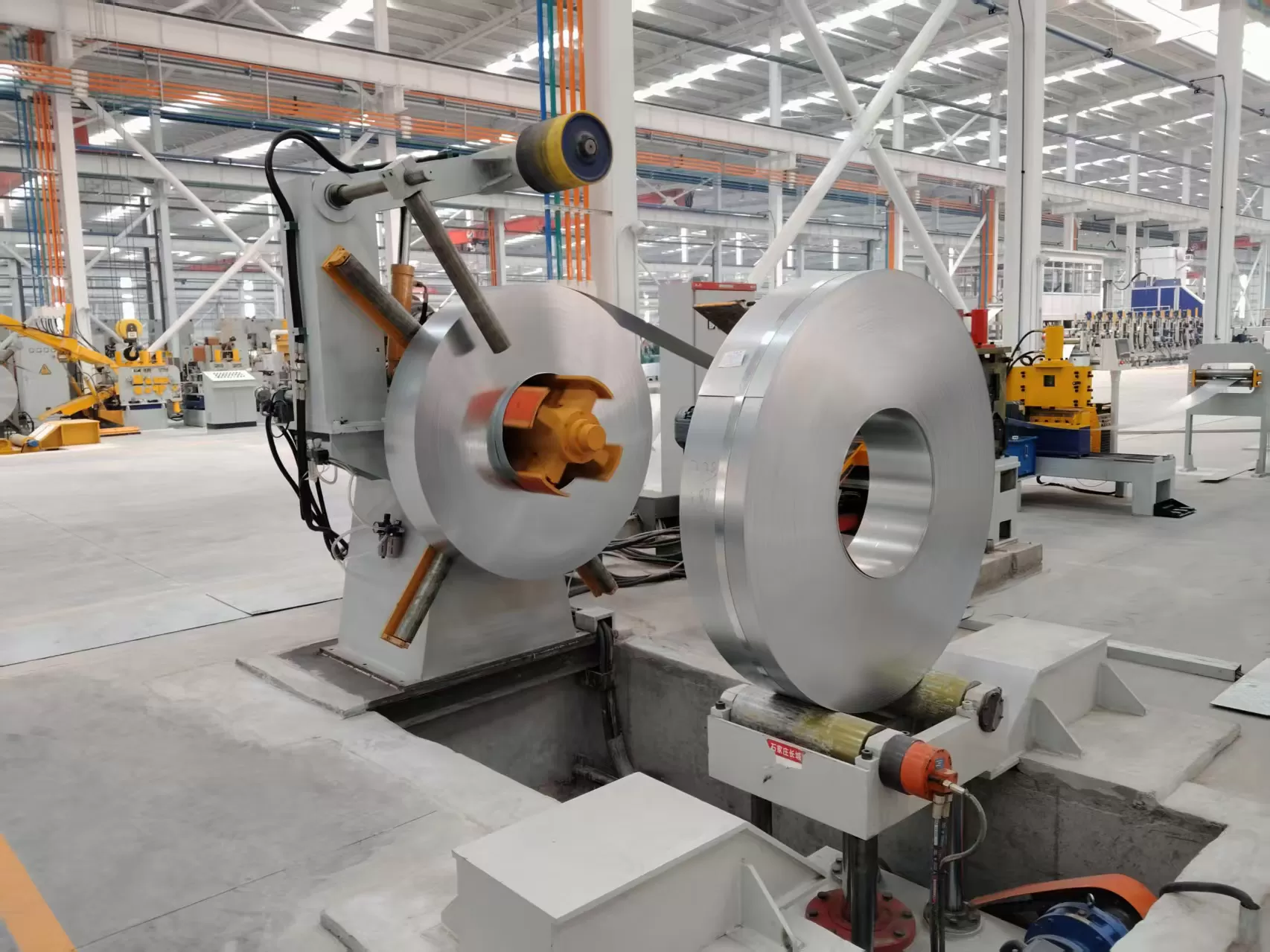
Single-Mandrel vs. Double-Cone Decoiler: Single-mandrel
units suit small to medium coil weights with high changeover flexibility.
Double-cone or double-stub decoilers are mandatory for ultra-heavy coils
exceeding 20 metric tons to eliminate cantilever shaft deflection.
Integrated Straightener vs. Pull-Through Straightener: Pull-through units rely on downstream forming stands to pull the strip, which
can cause edge stretching and line slippage on heavy gauges. Driven
straighteners power each work roll via dedicated distribution gearboxes,
providing controlled payout without putting mechanical drag on the forming
mill.
Surface Protection for Sensitive Alloys: When processing
stainless steel, aluminum, or galvanized material, polyurethane-coated hold-down
rolls and non-marking backup bearings prevent zinc flaking and cosmetic surface
scratching.
Frequently Asked Questions
What is the functional difference between a leveling machine and a standard
straightener?
A standard straightener uses a lower roll count (typically 5 to 7 rolls) and
larger roll diameters primarily to remove longitudinal coil set and crossbow. A
precision leveler utilizes smaller, closely spaced rolls supported by multi-tier
backup bearings, applying higher plastic deformation to remove complex shape
defects such as center buckles and edge waves.
How does improper straightener roll penetration affect high-frequency tube
welding?
Inadequate straightener roll penetration leaves residual stresses inside the
strip. When the strip passes through the breakdown and fin-pass passes, these
uneven stresses cause the strip edges to lift or drop unevenly. This mismatch
creates an offset V-angle at the welding point, causing uneven weld beads, cold
welds, and compromised seam burst strength.
Can a single decoiler and straightener handle both carbon steel and
high-strength alloy coils?
Yes, provided the machine design accounts for the highest yield strength
material in the product mix. Processing high-strength steels requires higher
motor torque, larger drive shaft diameters, increased machine frame rigidity,
and smaller roll pitches to reach the necessary plastic deformation zone without
exceeding machine stress ratings.
Why is back-tension control necessary during uncoiling?
Back-tension maintains positive engagement between the coil wraps and the
mandrel. Without continuous back-tension, inner wraps loosen (a condition known
as coil clock-springing), which causes sudden strip slippage, surface
scratching, strip tracking errors, and unstable entry into the straightener
pinch rolls.
How frequently should straightener work rolls be re-ground?
Re-grinding frequency depends on strip surface conditions (such as pickled
versus unpickled hot-rolled surfaces) and production throughput. Under standard
two-shift operations handling hot-rolled carbon steel, work rolls typically
undergo ultrasonic cleaning and inspection every 3 to 6 months, with surface
re-grinding performed once surface runout exceeds 0.02 mm.
Custom Engineering and Line Configuration
Tube manufacturing efficiency begins with precise strip conditioning at the
uncoiling stage. SANSO engineers custom high-yield strip preparation machinery
designed to meet specific factory floor layouts, coil handling capacities, and
complex metallurgical requirements. Submit your coil dimensions, material yield
ratings, and target line speeds to our engineering team to receive a detailed
layout specification and technical proposal for your upcoming mill
installation.