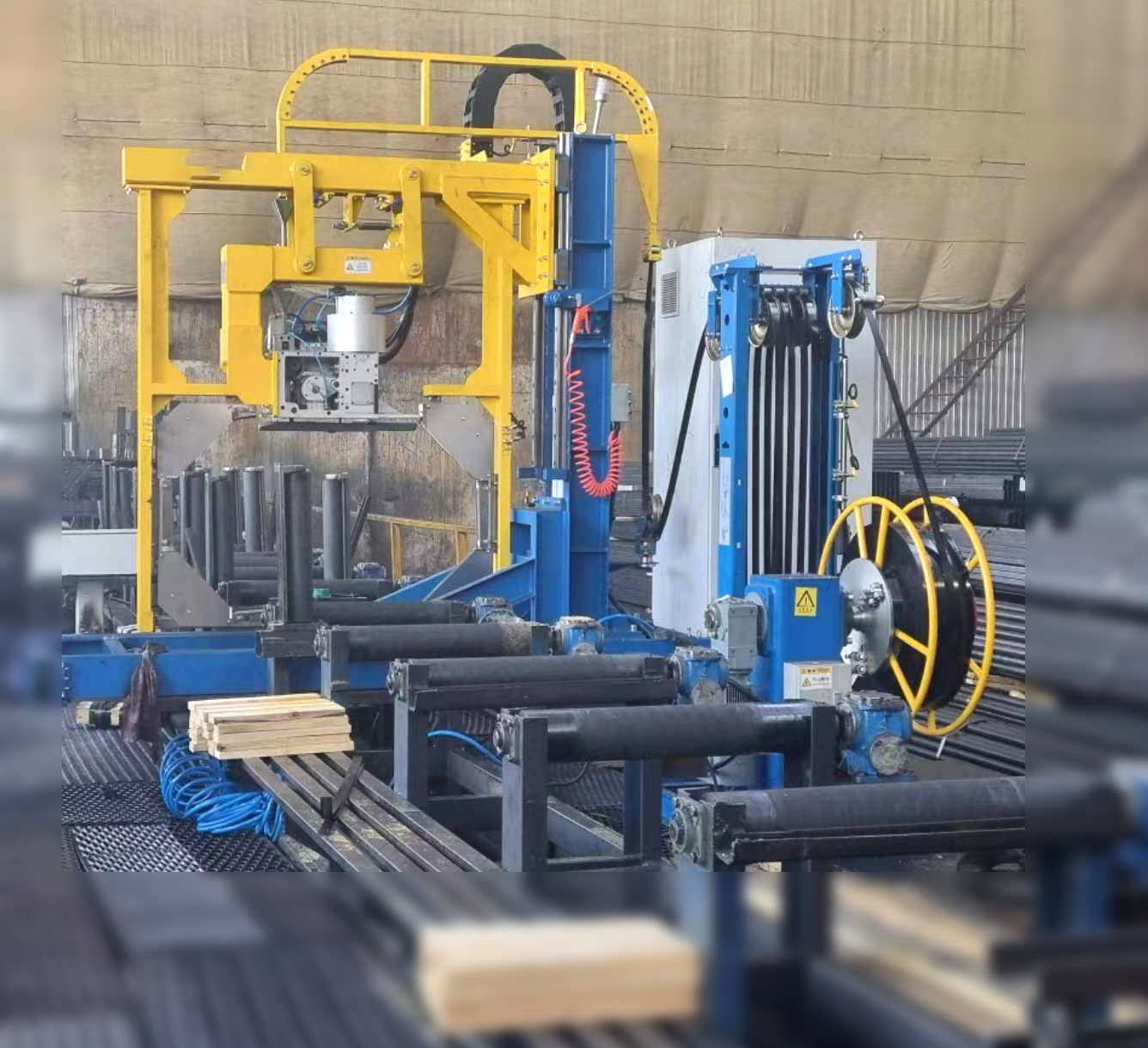
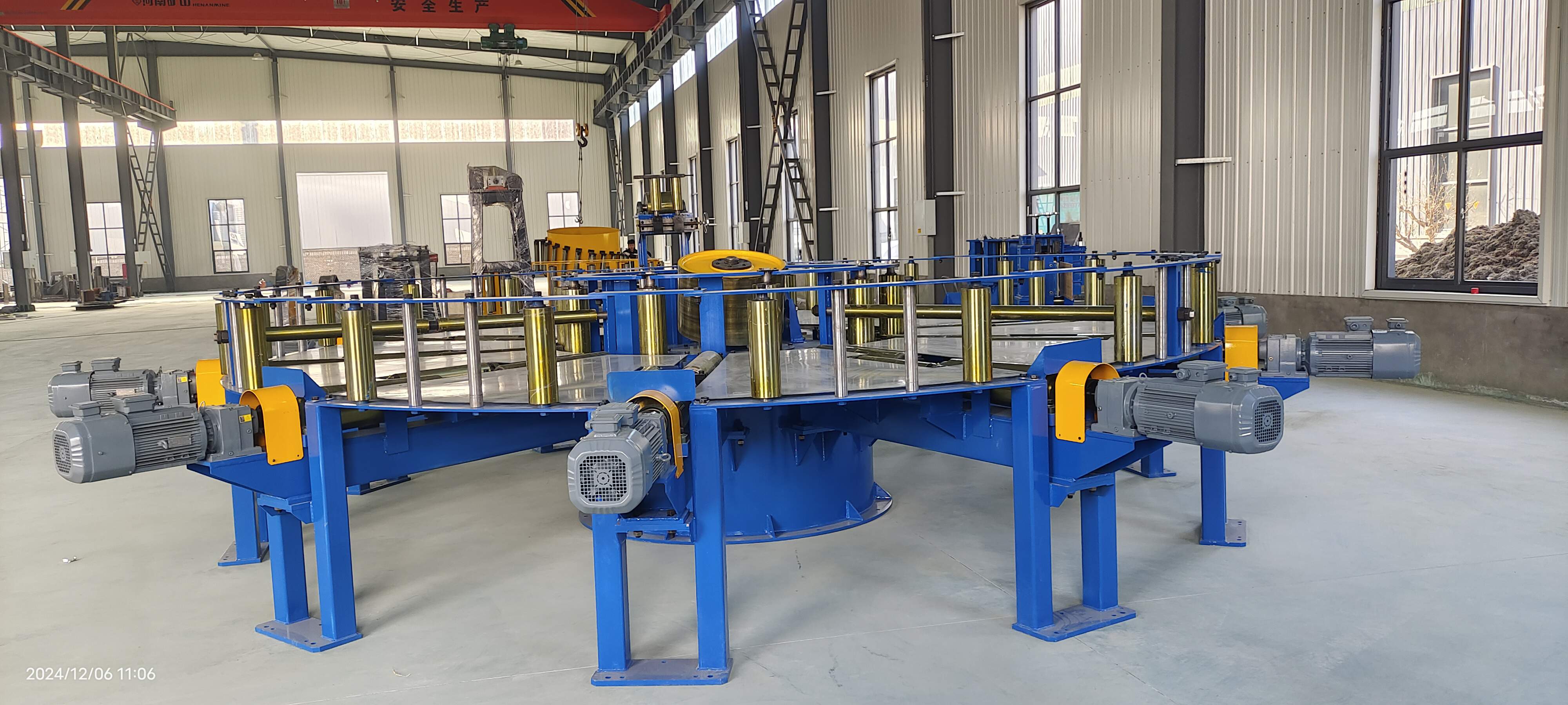
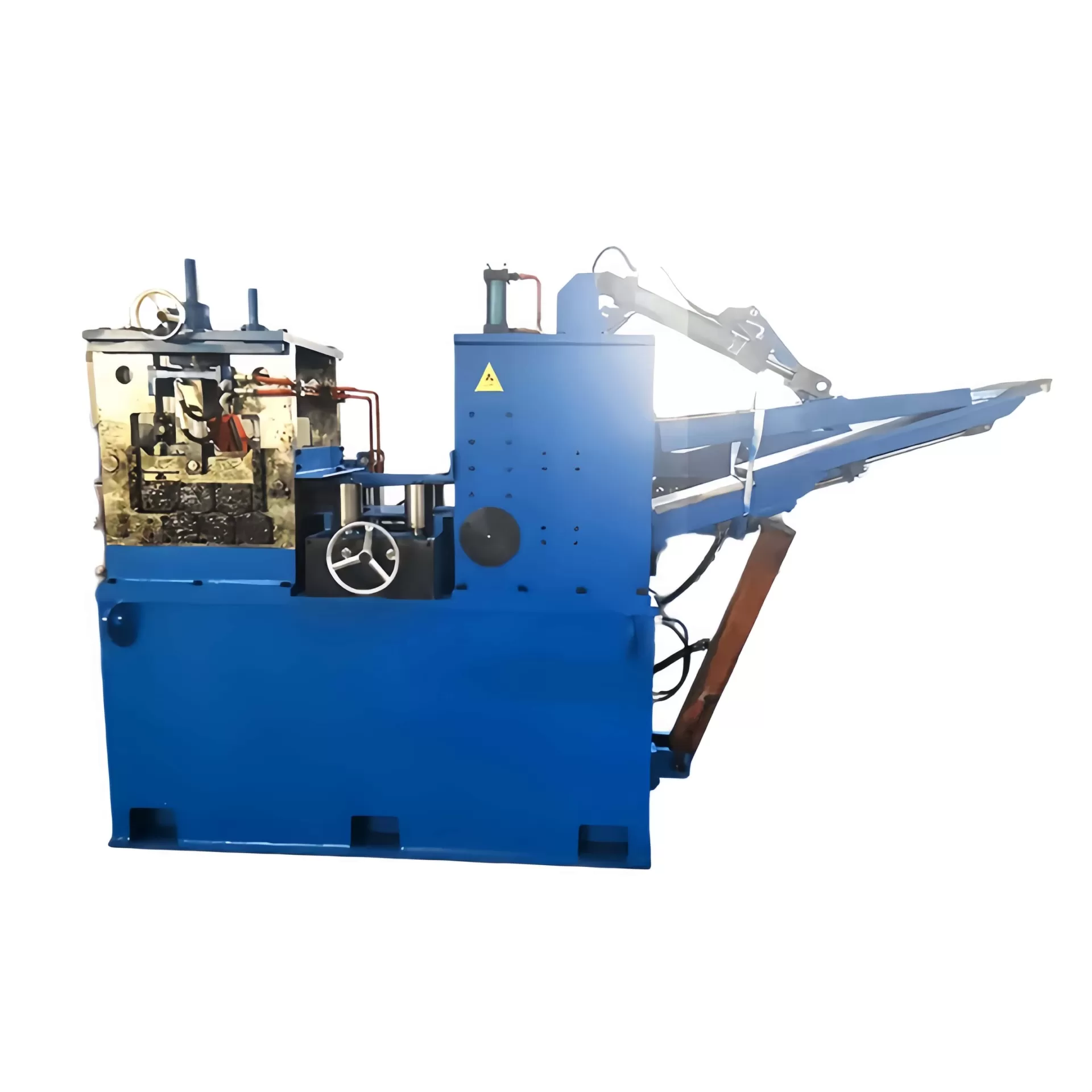
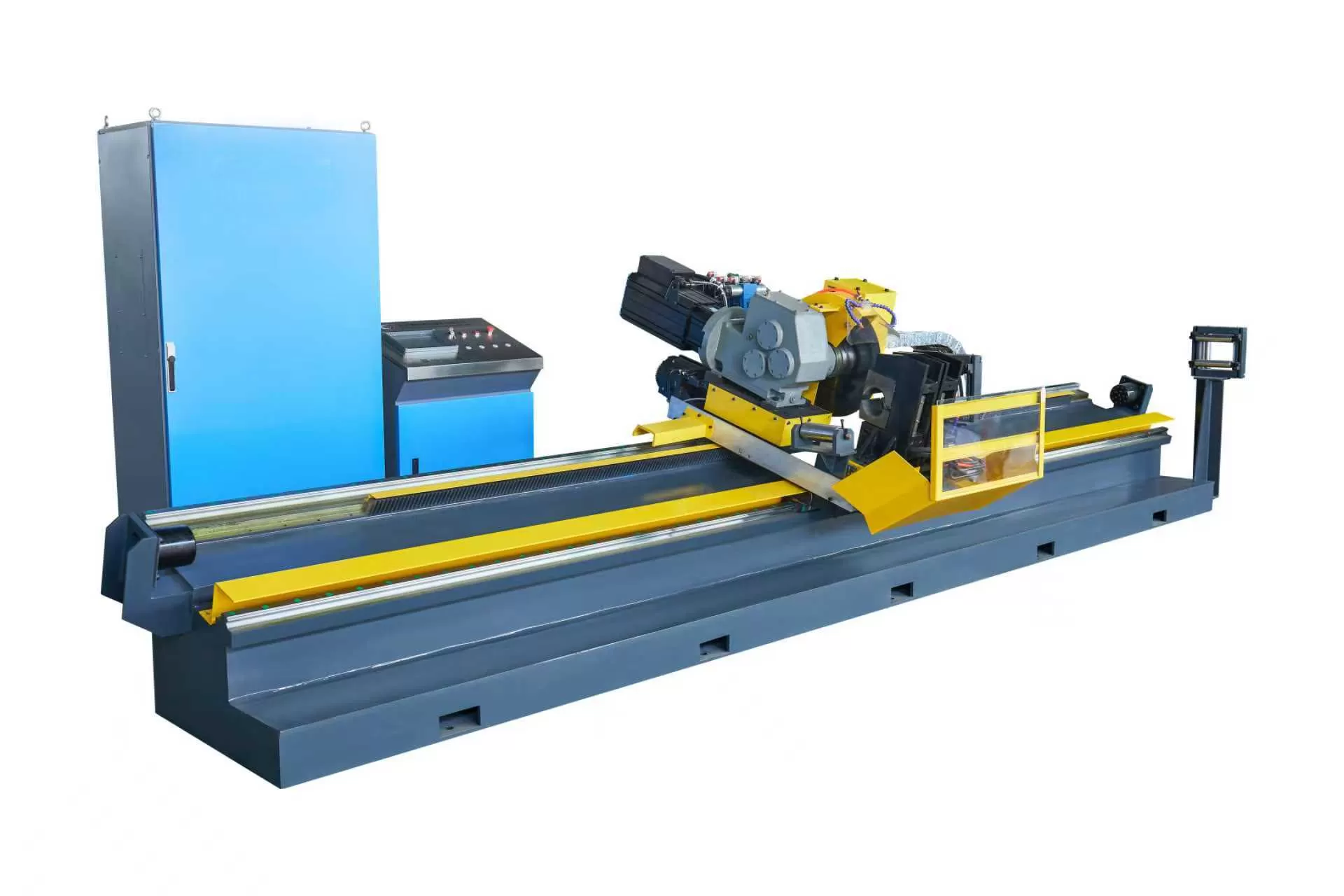
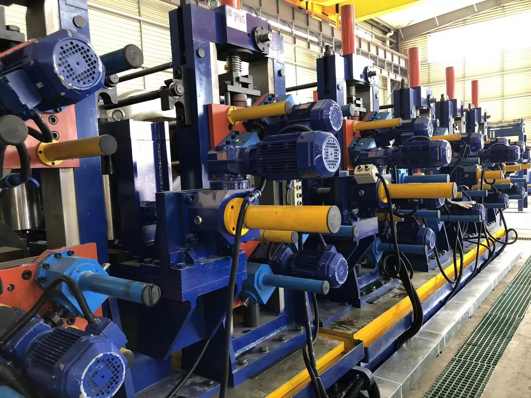
Automated metal stamping, roll forming, and electric resistance welded (ERW)
tube mill operations rely on precise continuous coil processing to maintain
dimensional consistency and high line speeds. At the core of this sequence is
the decoiler straightener feeder, a unified machine frame engineered to uncoil,
flatten, and index raw strip material directly into downstream forming or
cutting equipment. Combining these three distinct operational phases into a
single physical footprint reduces plant space consumption, eliminates material
handling delays, and prevents loop control instabilities typical of conventional
separated lines.
Heavy-duty processing machinery manufactured by SANSO incorporates reinforced
structural frameworks and proportional hydraulic controls to handle high-tensile
carbon steels, austenitic alloys, and hot-rolled structural plate stock.
Achieving predictable strip delivery requires matching raw material yield
characteristics with mechanical drive capacity, work roll geometric layouts, and
dynamic servo response rates.
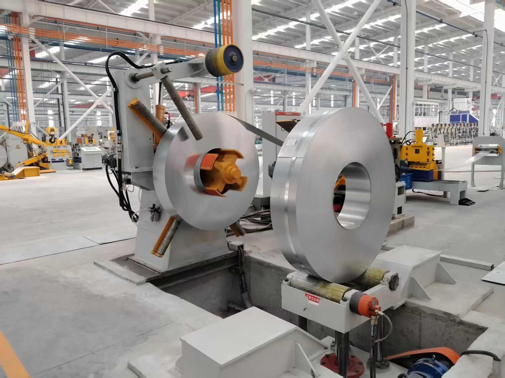
1. Structural Architecture and Mechanical Consolidation
Legacy processing lines separate the decoiling reel, flattening machine, and
indexing unit using broad floor-level slack pits. Implementing a compact
decoiler straightener feeder combines these three operational stages onto a
single heavy bed, eliminating material slack zones between processing heads.
This arrangement relies on driven hold-down rolls, threading peeler plates, and
synchronized entrance pinch rolls to guide thick material directly from the
outer coil radius into the leveling rolls without manual intervention.
Frame rigidity represents a primary design boundary. When processing
high-tensile steel, internal bending moments generated during alternate flexing
exceed the yield point of the strip, exerting high upward forces against the
upper roll housing. Structural deflection introduces uneven pressure across the
strip width, causing edge camber, twisting, and feed pitch variations. Heavy
steel side plates, tie-bar support structures, and pre-loaded bearing blocks
maintain parallel alignment under full structural load.
Decoiler Module Engineering
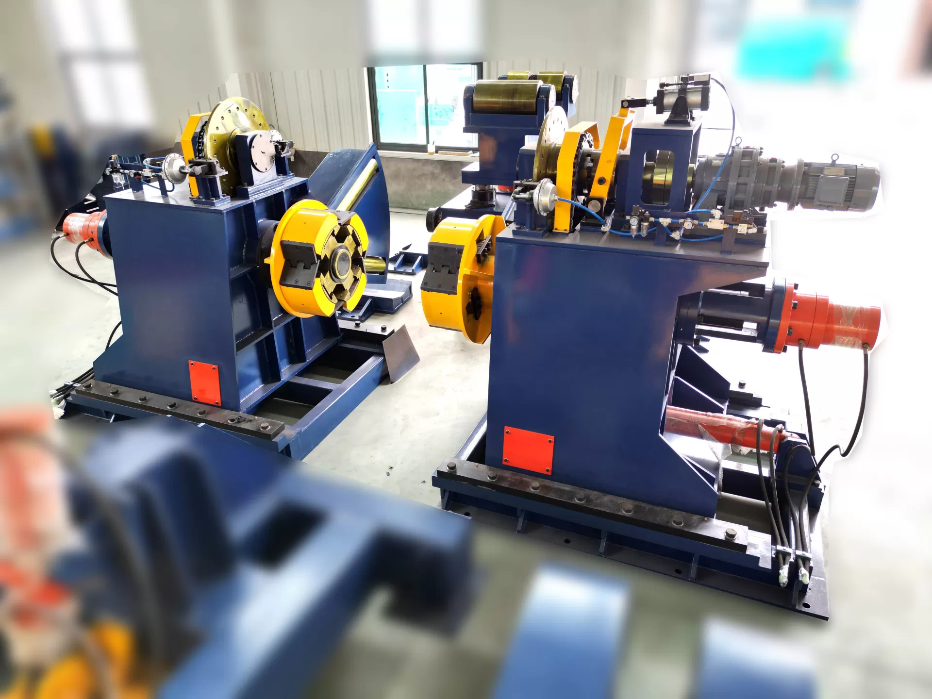
The uncoiler section carries heavy raw coil weights while maintaining
constant back-tension during fast indexing cycles. Mandrel expansion operates
via internal hydraulic wedge structures or multi-segment linkage arms,
delivering uniform radial pressure against the internal diameter of the coil
core.
Mandrel Clamping Mechanisms: High-pressure hydraulic
cylinders actuate an internal tension rod that shifts tapered expansion slides
outward. This provides maximum surface contact against the inner coil wraps,
preventing internal slippage during aggressive deceleration steps.
Dynamic Back-Tension Control: Pneumatic or hydraulic disc
brakes deliver adjustable braking force. Proper back-tension prevents unspooling
and maintains strip tracking along the center axis into the flattening
head.
Hydraulic Loading Cars: Heavy-duty lift cars transport raw
coils horizontally and vertically to center the coil onto the expansion shaft.
Side-support rollers stabilize narrow, large-diameter coils during horizontal
transport.
Hold-Down and Snubber Assemblies: Articulating arms
equipped with motor-driven urethane rollers exert downward pressure on the outer
coil wraps during band removal, guiding the leading edge safely into the
threading path.
Threading and Strip Entry Guidance
Guiding thick-gauge strip into the main roll stack requires automated
threading components to steer the material leading edge. Hydraulic peeler blades
extend upward to lift the outer wrap, while adjustable side-guide rollers align
the material along the mill centerline. Driven upper and lower pinch rolls grab
the leading edge and drive the stock forward until full engagement with the
straightener work rolls is achieved.
2. Metallurgy and Work Roll Deformation Physics
Raw coil stock retains permanent curvature, commonly referred to as coil set,
along with secondary geometric defects such as crossbow and edge wave.
Eliminating these defects requires subjecting the strip to alternate reverse
bending beyond its yield point. The straightener module forces the material
through elastic-plastic deformation, shifting internal tension and compression
zones across the material cross-section to establish a flat, stress-relieved
condition.
Work roll positioning follows a converging geometric pattern. The entrance
rolls apply deep penetration to bend the strip past its yield point, while the
exit rolls gradually return to a parallel alignment to set final flatness.
Operating a heavy-duty decoiler straightener feeder ensures that alternate
bending moments are applied symmetrically, preventing residual stress imbalance
from re-introducing curvature after forming or welding operations.
Roll Diameter and Pitch Geometry
Work roll diameter and center distance dictate the material thickness limits
and yield strength threshold a machine can process. Smaller roll diameters allow
tighter bend radii, making them suitable for thin-gauge stock where fine surface
flatness is mandatory. Conversely, larger roll diameters and wide roll pitches
are required for heavy plate to prevent roll shaft shear and bearing
overload.
Engineering teams at SANSO design specialized work-roll geometries using
high-carbon alloy steels such as SUJ2 or DIN 1.3505. These components undergo
deep induction hardening to HRC 60 or higher, followed by precision grinding and
hard chrome plating. This surface treatment withstands continuous abrasion from
heavy mill scale, oxide particles, and aggressive metalworking fluids.
Back-Up Roll Systems
To resist deflection across broad strip widths, intermediate and primary
back-up roller banks support the work rolls. Without adequate back-up support,
work rolls bow vertically under load, resulting in center buckle or wavy edges
on the finished strip.
Stationary Shaft Back-Ups: Standard configurations utilize
precision needle bearings mounted on rigid stationary shafts to provide
continuous vertical support to the work rolls.
Flight-Adjustable Back-Ups: Advanced machines feature
wedge-adjusted back-up roller banks, allowing operators to apply localized
upward thrust to compensate for raw material crown variations or edge wave
defects.
3. Servo Drive Dynamics and Feed Precision
Feeding precision impacts tool life, seam alignment, and component tolerance
integrity. High-torque AC servo motors drive the feeding mechanism through
planetary reduction gearboxes, delivering rapid acceleration profiles combined
with precise positional stopping.
During progressive stamping operations, the feed rolls must briefly release
pressure on the strip at the bottom of the press stroke. This pilot release
sequence allows locating pins within the die to position the material
accurately. Pneumatic or hydraulic pilot release mechanisms mechanically lift
the upper roll assembly away from the strip in milliseconds, re-engaging the
material as the press stroke ascends.
Integrating a compact decoiler straightener feeder into a continuous tube
mill line requires precise speed synchronization rather than intermittent
indexing. Absolute rotary encoders mounted directly to the lower work roll or
dedicated measuring wheel monitor linear strip velocity, feeding positional
feedback to the main line controller to correct speed drift in real time.
4. Process Parameter Selection and Equipment Sizing
Specifying appropriate coil processing machinery requires evaluating material
yield boundaries, line speed profiles, and spatial parameters. Over-specifying
motor torque without addressing roll shaft fatigue limits causes mechanical
failure, whereas under-specifying coil weight limits restricts material sourcing
options.
The structural layout and drive train ratings are primary criteria when
sizing machinery for high-yield alloys. Advanced High-Strength Steels (AHSS)
require substantial torque reserves and reinforced roll adjustment motors to
maintain penetration control during continuous operations.
| Operational Parameter | Low Carbon Steel (< 250 MPa Yield) | High-Tensile Steel (> 590 MPa Yield) |
|---|
| Roll Penetration Force | Standard baseline force calculations. | Requires 1.5x to 2.2x increased downward force. |
| Work Roll Diameter | Standard diameters maximize thickness range. | Smaller pitch with reinforced backup rolls to prevent flex. |
| Drive Motor Torque | Calculated based on basic inertia loads. | High-torque AC servo systems with enlarged gearboxes. |
| Pilot Release Response | Standard pneumatic lift execution. | High-speed hydraulic lift with dampening control. |
Control Systems and Recipe Storage
Modern industrial control interfaces feature program recipe memory, enabling
operators to store roll height positions, feed pitch lengths, acceleration
curves, and brake tension settings for specific material batches. Motorized work
roll adjustment equipped with digital linear encoders decreases setup intervals
during coil changeovers, reducing operator error and material scrap during line
initialization.
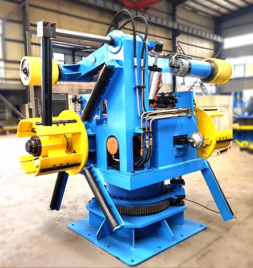
5. Maintenance Protocols and Troubleshooting
Sustained operational accuracy relies on structured preventive maintenance
schedules. The high mechanical loads involved in uncoiling and flattening heavy
strip stock generate ongoing wear on bearings, drive gears, hydraulic seals, and
electrical feedback devices.
Roll Surface Cleaning: Mill scale, oxide dust, and drawing
lubricants accumulate on work roll surfaces. Operating with dirty rolls indents
soft materials and reduces drive traction on heavy plates. Scraper blades and
manual solvent cleaning maintain roll surface condition.
Centralized Lubrication: Main roll bearings, back-up roller
shafts, and drive gear trains require continuous grease application. Automated
lubrication systems inject measured amounts of extreme-pressure grease at set
operational intervals, preventing dry friction wear under high radial
forces.
Drive Train Inspection: Gear trains transmitting torque
between work rolls experience reversal loads during start-stop indexing.
Periodic gear backlash measurements and drive chain tension checks prevent
mechanical play from compromising feed accuracy.
Hydraulic Fluid Conditioning: Expansion mandrels and pilot
release units rely on clean fluid. Regular filter element replacements and fluid
contamination analysis prevent valve sticking and cylinder seal
erosion.
Equipment engineered by SANSO utilizes accessible roll cassette designs and
modular hydraulic manifolds, facilitating straightforward maintenance access and
reducing downtime during overhaul schedules.
Frequently Asked Questions
Q1: What is the primary operational advantage of a 3-in-1 decoiler
straightener feeder compared to conventional split lines?
A1:
Combining uncoiling, leveling, and feeding functions onto a single machine frame
eliminates the requirement for long floor slack loops. This setup reduces total
footprint requirements, simplifies control integration, accelerates threading
procedures, and improves operational safety during material loading.
Q2: How does material yield strength influence equipment
selection?
A2: Higher yield strength materials resist plastic
deformation, requiring greater penetration force from the straightener rolls.
This increases drive motor torque demands, requires heavier frame construction
to resist deflection, and necessitates back-up roll assemblies to support the
work rolls under high loads.
Q3: Why is the pilot release function used in progressive die
stamping?
A3: The pilot release function momentarily lifts the upper
feed roll off the strip while die locating pins enter the material pilot holes.
This releases grip friction, allowing the pins to align the strip precisely
before die closure, preventing cumulative feed pitch errors and tooling
damage.
Q4: What measures prevent material slippage during fast feed
cycles?
A4: Material slippage is managed by adjusting clamping
pressure on the entrance and exit pinch rolls, maintaining clean roll surfaces
free of fluid build-up, utilizing hardened matte-finish rolls, and setting
appropriate acceleration profiles on the AC servo drive.
Q5: What factors indicate the need for intermediate or back-up roll
supports?
A5: Back-up support systems are necessary when processing
wider strip dimensions, heavy wall thicknesses, or high-tensile alloys. Under
heavy loading, slender work rolls flex centrally without support, leading to
non-uniform stress distribution and edge wave across the strip width.
Inquire for Custom Engineering Specifications
Selecting appropriate drive configurations, roll geometries, and automation
controls for your production requirements involves detailed evaluation of
material properties and line dynamics. Submit your mill parameters and material
requirements to the engineering team at SANSO to receive a detailed system
analysis and request a proposal for a custom decoiler straightener feeder
configuration built to your specifications.