In high-volume metal processing operations, uncoiling is often an overlooked
bottleneck. Handling multi-ton coils of cold-rolled steel, galvanized sheet,
aluminum, or stainless steel presents severe mechanical challenges. Manual and
lightweight mechanical unwinding methods frequently result in uneven feeding,
material camber, coil slippage, and unacceptable workplace hazards. A
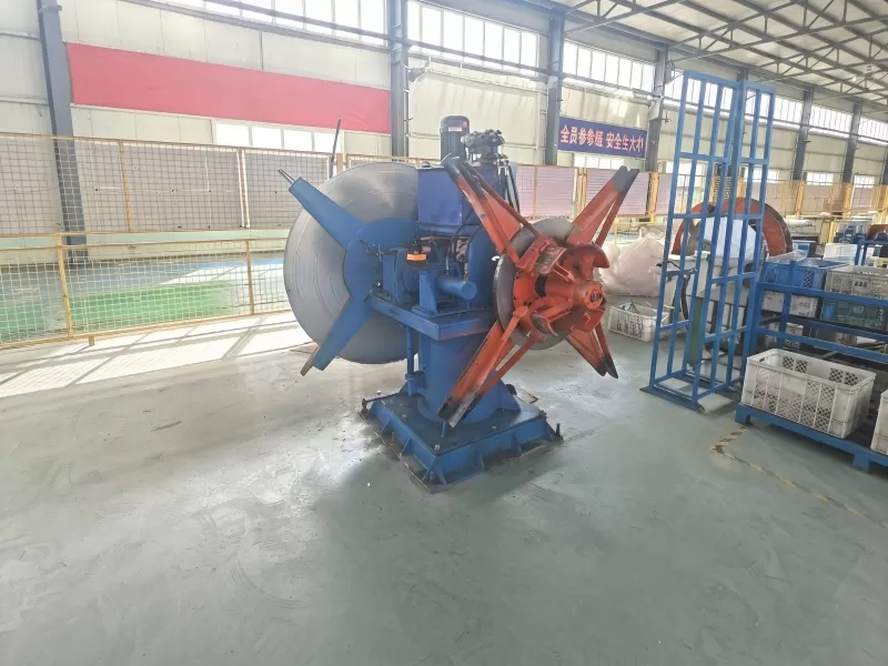
high-specification hydraulic decoiler machine serves as the
critical foundation for modern coil processing lines, ensuring precise tension,
smooth material delivery, and robust structural safety.
Engineered to handle coil loads ranging from 3 metric tons to over 20 tons, a
hydraulic uncoiler uses fluid power to drive mandrel expansion, hold heavy raw
material securely, and synchronize unwinding speed with downstream equipment
such as roll formers, cut-to-length (CTL) lines, slitting systems, and
high-speed stamping presses. Engineering teams at SANSO design
these units to eliminate rotational vibration, maintain minimal radial runout,
and maximize overall equipment effectiveness (OEE).
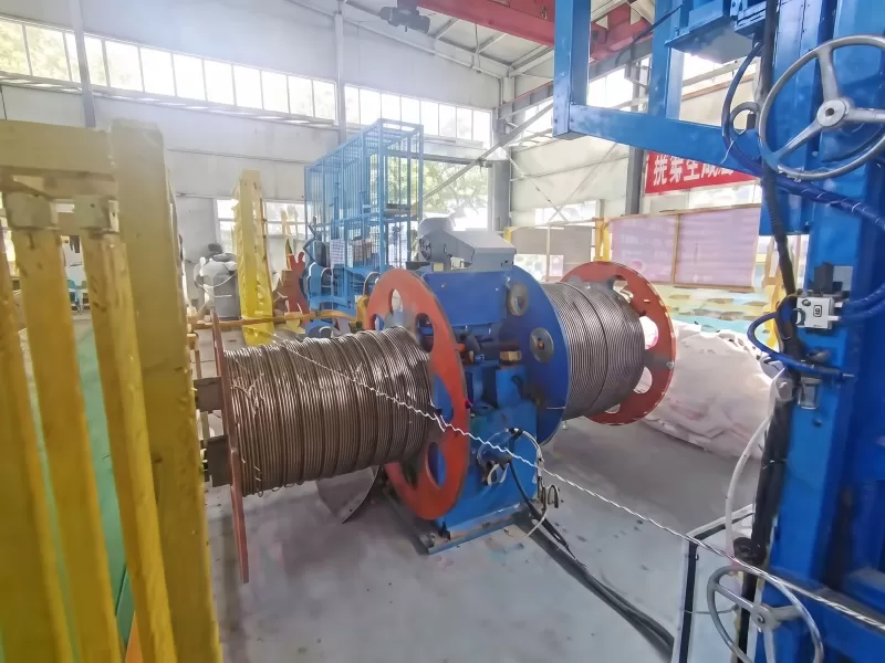
The Engineering Reality Behind High-Tonnage Coil Unwinding
When handling steel coils exceeding 5 tons, raw rotational inertia and
tension variations create continuous mechanical stress. Conventional screw-type
or friction-based decoilers fail under these demands due to structural
deflection, inconsistent clamping force, and manual adjustment delays. A
hydraulic decoiler machine solves these issues through inherent
mechanical and hydraulic advantages:
High Power Density: Hydraulic actuation yields immense
radial clamping force within a compact footprint, eliminating heavy mechanical
linkages, gears, or wear-prone mechanical wedges.
Positive Radial Expansion: Hydraulic pressure expands the
mandrel segment plates uniformly against the coil's inside diameter (ID). This
continuous radial load prevents coil slipping during high-torque acceleration
and sudden emergency stops.
Incompressible Fluid Precision: Because hydraulic oil is
virtually incompressible, system pressure remains stable throughout the
unwinding cycle. This precise force regulation eliminates slack and prevents
coil "clock-springing" (uncontrolled unwinding of outer coil wraps).
Integrated Operational Safety: Built-in hydraulic check
valves retain clamping pressure even in the event of a sudden electrical power
interruption, preventing catastrophic coil release.
Anatomy of Precision: Core Components of a Commercial Hydraulic Decoiler
Machine
Understanding the internal engineering of a modern uncoiler allows plant
managers and equipment specifiers to evaluate structural durability and
operational reliability.
1. High-Rigidity Mandrel Assembly
The mandrel is the core load-bearing spindle subjected to intense dynamic
bending moments. Premium mandrels are forged from high-carbon chromium manganese
alloy steel (such as En 31 grade), heat-treated to 58–60 HRC. To prevent
rotational deflection and ensure maximum concentricity, thin-walled Chrome
Vanadium steel cylinder sleeves—heat-treated to a tensile strength of 1300
N/mm²—are shrink-fit onto the spindle body. This meticulous construction keeps
total radial runout below 0.005 mm Total Indicator Reading (TIR), preventing
tool chatter and uneven wear in downstream press dies.
2. Hydraulic Expansion Circuit
Mandrel expansion relies on a central hydraulic cylinder driving an axial
wedge mechanism or toggle link assembly. Operating at system pressures up to 20
MPa, the hydraulic cylinder forces four or six expansion segments outward to
grip inner coil diameters ranging from 470 mm to 530 mm (or up to 610 mm with
extension shoes). Reversing fluid flow retracts the segments rapidly for fast
coil changeovers.
3. Drive Motor, VFD, and Dynamic Braking
Rotational torque is supplied by an AC geared motor or direct hydraulic motor
managed by a Variable Frequency Drive (VFD). The drive system adjusts uncoiling
velocity dynamically based on feedback from downstream equipment. Integrated
pneumatic or hydraulic disc brakes apply exact holding torque during stop cycles
to keep the feed loop stable without stretching or scratching sensitive sheet
surfaces.
4. Hydraulic Coil Car (Loading System)
For heavy coils (10T–20T+), loading via overhead crane presents severe safety
risks and long downtime. An integrated hydraulic coil car features a V-shaped
cradle mounted on a motorized rail platform. Driven by vertical hydraulic
cylinders, the car aligns the coil perfectly with the mandrel center line,
slides the coil horizontally onto the spindle, and lowers safely—reducing coil
loading times from 20 minutes to under 3 minutes.
5. Snubber Arm / Hold-Down Pressing Arm
Equipped with a heavy-duty polyurethane-coated roller, the hydraulic pressing
arm applies top-down pressure on the outer coil wraps during band cutting and
initial thread-up. This prevents spring-steel materials from snapping open and
causing operator injury.
Technical Specifications & Selection Parameters
When selecting a hydraulic decoiler machine for industrial
line integration, evaluate raw material yield strength, coil dimensions, and
operational duty cycles against these baseline specifications:
| Specification Parameter | Standard Duty Specification | Heavy Duty / Heavy Tonnage Specification |
|---|
| Coil Weight Capacity | 3,000 kg – 5,000 kg (3T – 5T) | 10,000 kg – 25,000 kg+ (10T – 25T+) |
|---|
| Material Width Range | 200 mm – 1,000 mm | 600 mm – 1,800 mm |
|---|
| Material Thickness Range | 0.3 mm – 3.2 mm | 1.0 mm – 8.0 mm+ |
|---|
| Coil Inner Diameter (ID) | φ450 mm – φ530 mm | φ480 mm – φ610 mm (with pad extensions) |
|---|
| Max Coil Outer Diameter (OD) | φ1,300 mm – φ1,500 mm | φ1,600 mm – φ2,000 mm |
|---|
| Uncoiling Speed | 0 – 25 m/min (VFD controlled) | 0 – 35 m/min (Synchronized Servo/VFD) |
|---|
| Hydraulic Working Pressure | 12 MPa – 16 MPa | 16 MPa – 21 MPa |
|---|
Comparative Analysis: Mechanical vs. Pneumatic vs. Hydraulic Uncoilers
Selecting the wrong actuation technology can result in premature equipment
failure, limited line speed, and frequent maintenance downtime. Below is an
engineering comparison across common uncoiling systems:
| Performance Feature | Mechanical / Manual Screw | Pneumatic Expansion | SANSO Hydraulic Decoiler Machine |
|---|
| Max Tonnage Capacity | Limited (≤ 3 Metric Tons) | Moderate (≤ 5 Metric Tons) | Extreme (≤ 30+ Metric Tons) |
|---|
| Mandrel Clamping Force | Low (Operator-dependent wrench tension) | Medium (Restricted by air pressure limits) | High (Hydraulic relief valve regulated) |
|---|
| Coil Slippage Risk | High under fast braking | Moderate with heavy coils | Virtually Zero (Positive pressure grip) |
|---|
| Loading Safety | Low (Manual pry bar intervention) | Moderate | Maximum (Fully automated coil car integration) |
|---|
| Operational Duty Cycle | Light / Intermittent | Medium / Standard Batch Production | Heavy-Duty / Continuous 24/7 Operations |
|---|
Strategic Automation Levels & Line Synchronization
A hydraulic decoiler machine does not operate in isolation;
it functions as the head of an integrated processing line. Depending on
production targets, choose the appropriate automation configuration:
Semi-Automatic Systems: Feature hydraulic mandrel expansion
and hydraulic coil car loading, but require manual operator control for loop
monitoring and edge guide adjustments. Ideal for mid-volume stamping lines and
flexible job shops.
Fully Automatic Integrated Lines: Connected directly to
main line PLC panels (Siemens/Mitsubishi). Uncoiling speed is controlled
continuously via loop control sensors—such as ultrasonic displacement devices,
laser distance sensors, or photo-electric proximity switches. The system
accelerates, decelerates, and stops automatically without operator
intervention.
Common Application Environments
Modern manufacturing sectors rely heavily on hydraulic uncoiler technology to
maintain production feed rates:
Automotive Stamping: Feeds high-strength steel (AHSS) and
aluminum blanks to multi-station press lines for chassis structural members and
body panels.
Roll Forming & Construction Material: Feeds galvanized
coils into high-speed C/U channel, roofing panel, and structural purlin roll
formers.
Steel Service Centers: Functions as the entry pay-off reel
for high-speed slitting lines and precision cut-to-length (CTL) shearing
systems.
HVAC & Appliance Manufacturing: Delivers scratch-free
painted or stainless steel strips to automated shell forming lines.
Quantifiable ROI: Efficiency, Material Yield, and Safety
Upgrading to a heavy-duty hydraulic decoiler machine from
SANSO yields measurable returns across three primary operating
metrics:
1. OEE Elevation via Reduced Changeover Downtime
Manual coil mounting and mechanical mandrel expansion on a 10-ton coil can
require 20 to 30 minutes of crane hold time and manual labor. With a SANSO
hydraulic uncoiler equipped with an automated coil car and rapid hydraulic
expansion, coil changeover is completed in under 4 minutes. On a two-shift
operation changing 8 coils daily, this saves over 3 hours of line downtime every
day.
2. Elimination of Material Scrap & Surface Damage
Coil slippage on mechanical mandrels damages the inner turns of expensive raw
steel, forcing shops to scrap up to 3% of every coil. Hydraulic expansion
provides equal radial force across the full inner contact area, completely
eliminating slippage scars, inner sleeve distortion, and strip edge camber.
3. Industrial Risk Mitigation
Handling unstrapped heavy coils manually exposes floor operators to extreme
crushing and pinching hazards. Automated hold-down arms, hydraulic end-support
stands, and remote-control loading cars remove operators from high-risk hazard
zones, improving factory safety compliance.
Preventative Maintenance Protocol & Troubleshooting Guide
To preserve radial accuracy and protect high-pressure hydraulic components
over decades of continuous operation, implement a strict preventive maintenance
routine.
Preventative Maintenance Checklist
Hydraulic Fluid Management: Inspect fluid levels daily.
Perform fluid sampling every 1,000 operating hours to check for particulate
contamination or oxidation. Replace oil and high-pressure inline filter elements
per manufacturer guidelines (typically ISO VG 46 anti-wear hydraulic oil).
Seal & Hose Inspections: Visually inspect cylinder rod
seals, rotary hydraulic joints, and high-pressure flexible hoses weekly for
signs of weeping, abrasion, or cracking.
Mechanical Lubrication: Grease mandrel sliding wedges, link
pins, and coil car track bearings weekly using extreme-pressure lithium
grease.
Spindle Alignment Verification: Check mandrel center line
level and alignment relative to the straightener/feeder passline using precision
laser alignment tools every six months.
Field Troubleshooting Guide
| Symptom | Root Cause Analysis | Corrective Engineering Action |
|---|
| Mandrel loses expansion pressure during operation | Worn internal cylinder piston seals; leaking hydraulic check valve;
incorrect relief valve setting. | Inspect and replace cylinder seals; clean or replace pilot-operated check
valve; reset main system relief pressure to factory specification. |
|---|
| Jerky, uneven coil rotation during unwinding | Proportional speed control out of calibration; VFD drive parameters
improperly tuned; air trapped in hydraulic brake line. | Recalibrate loop sensor gain parameters; adjust VFD
acceleration/deceleration ramps; bleed air from dynamic brake circuit. |
|---|
| Excessive oil temperature (>60°C) | Clogged return line filter; hydraulic pump cavitation; continuous pressure
relief blowing due to valve jam. | Clean/replace return filter; verify oil reservoir level and pump suction
line; flush and inspect directional control valves. |
|---|
| Coil slippage on mandrel segments | Insufficient hydraulic clamping pressure; worn segment grip serrations;
incorrect ID expansion pads installed. | Verify hydraulic pressure gauge reading; clean or re-machine segment surface
serrations; install correct size ID extension shoes. |
|---|
Future-Proof Your Processing Line with SANSO
In high-speed metal stamping and roll forming, your downstream machinery is
only as productive as the entry decoiling system. A lightweight or outdated
uncoiler slows overall line velocity, creates quality defects, and exposes your
workforce to unnecessary risks. SANSO manufactures heavy-duty,
industrial-grade hydraulic decoiler machines designed to
perform reliably under the most demanding manufacturing conditions.
Whether you require a standard 5-ton uncoiler or a fully customized 20-ton
automated coil processing station with integrated coil cars and loop control
systems, SANSO engineers deliver tailored equipment built to maximize yield,
safety, and long-term operating profit.
Ready to optimize your coil feeding operations? Contact the
B2B engineering team at SANSO today to request a comprehensive technical
consultation, custom CAD line layout, and competitive commercial quotation for
your next project.
Frequently Asked Questions (FAQ)
A: Standard SANSO hydraulic decoilers accommodate coil weights from 3 metric
tons (3T) to 20 metric tons (20T). Custom structural frames and high-capacity
mandrels can be engineered for specialized heavy industrial applications
exceeding 30 tons.
Q2: How does hydraulic expansion compare to manual or pneumatic expansion
systems?
A: Hydraulic expansion provides significantly higher radial force, making it
essential for heavy coils (over 3–5 tons) and high-tension feeding applications.
Manual expansion is labor-intensive and speed-limited, while pneumatic systems
lack the force density required to hold heavy metal coils securely without
slippage.
Q3: Can a hydraulic decoiler machine handle non-standard inner coil
diameters?
A: Yes. While standard mandrels accommodate inner diameters between 470 mm
and 530 mm, SANSO provides quick-change modular extension shoes (pad adapters)
that allow the same mandrel to clamp larger coil IDs up to 610 mm or custom
sizes smoothly.
Q4: Why is dynamic braking important on a hydraulic uncoiler?
A: Dynamic braking prevents the high rotational inertia of a heavy coil from
pushing excess material forward when downstream straighteners, feeders, or
presses stop suddenly. It eliminates strip slack, loop overflowing, and surface
scratching.
Q5: How does the loop control system synchronize uncoiling speed with
downstream equipment?
A: The system uses non-contact ultrasonic or photo-electric loop sensors to
measure the depth of the material slack loop continuous. This signal is fed
directly into a Variable Frequency Drive (VFD), which adjusts the hydraulic
decoiler motor speed automatically to match line demand.