Continuous material feed is a fundamental requirement in high-output welded
pipe production and roll forming operations. At the entry point of these lines,
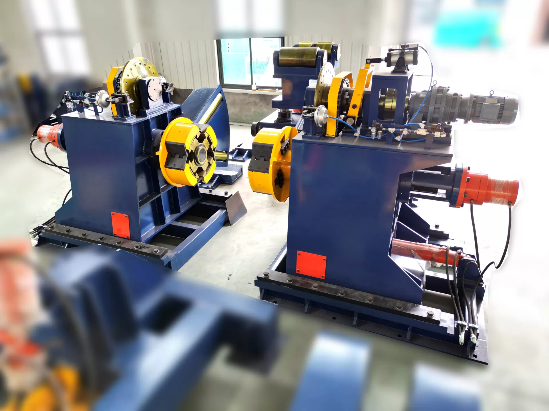
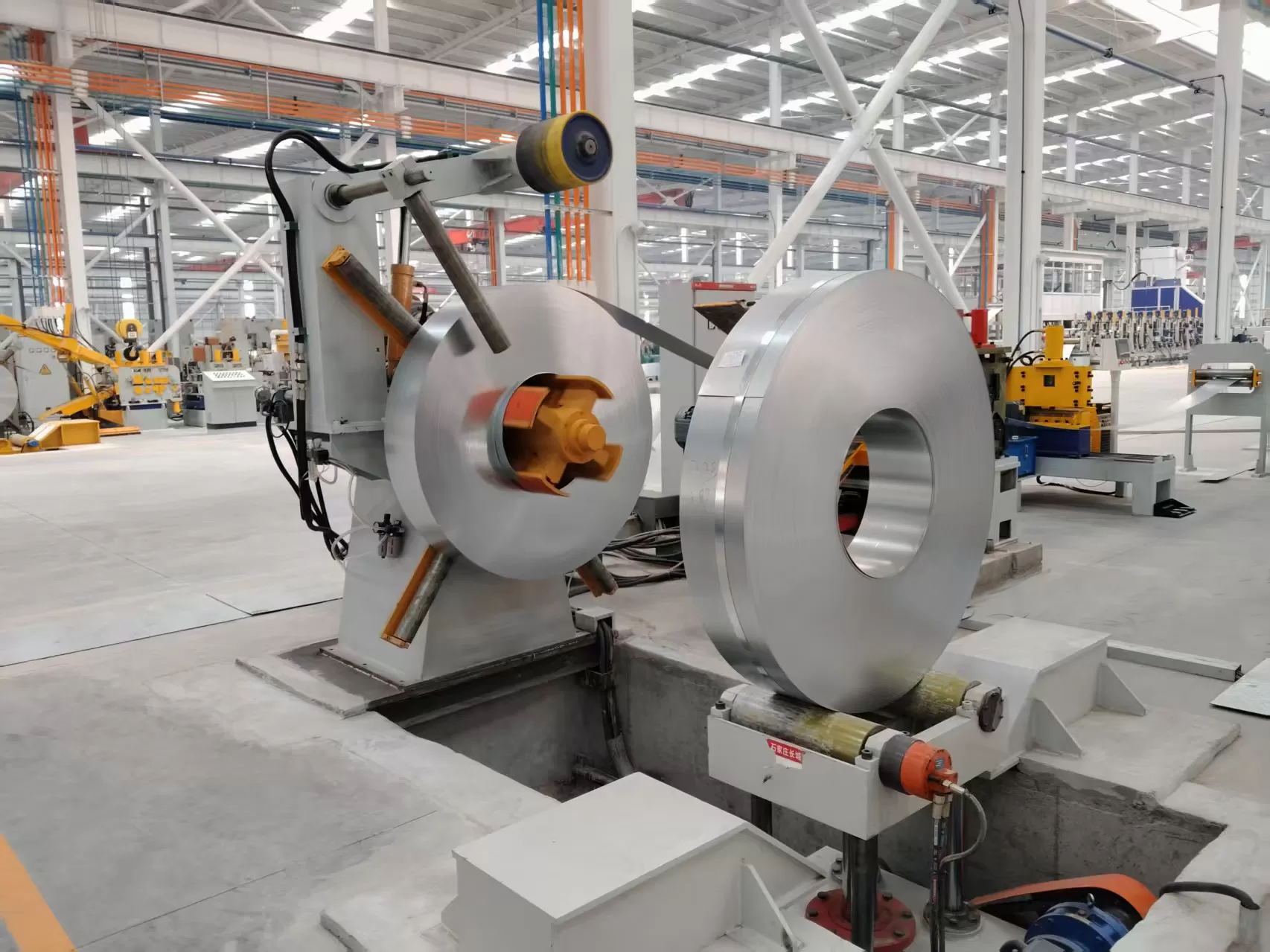
the steel coil decoiler serves as the primary mechanism for holding, centering,
and unwinding heavy coils of steel strip. This machine must manage high-torque
loads, control structural inertia, and deliver smooth strip tension to
downstream components. For manufacturers using tube mill lines, selecting a
robust feed system directly impacts product quality, roll tooling life, and
operational uptime. As a dedicated manufacturer of sheet metal machinery, SANSO
supplies heavy-duty uncoiling systems engineered to withstand continuous
industrial operation. This analysis explores the design mechanics, operational
challenges, and system integration strategies that define industrial uncoiling
performance.
Structural Mechanics of Mandrel Expansion and Support
The main spindle of a steel coil decoiler must bear significant cantilevered
weight. Heavy-duty metal coils typically range from 5 to 20 metric tons, placing
extreme radial and bending stresses on the main shaft bearings. To prevent shaft
deflection and bearing fatigue, industrial uncoilers use high-alloy forged steel
spindles housed within robust cast or fabricated steel housings. The bearings
supporting this assembly are typically heavy-duty spherical roller bearings
designed to manage both axial thrust and high radial loads.
The mechanism by which the mandrel grips the inner diameter of the coil is
vital for slip-free operation. Two main expansion designs dominate the
market:
Wedge-Type Expansion: A central drawbar, actuated by a
hydraulic cylinder, pulls a series of tapered wedges along the shaft. This axial
movement is converted into radial expansion, forcing the mandrel segments
outward in a uniform circular pattern. This design provides high clamping forces
and is suitable for heavy coils where inner wrap distortion must be
prevented.
Link-Type Expansion: Mandrel segments are connected to the
central shaft via a series of mechanical links. While suitable for lighter
applications, link systems require careful lubrication and maintenance to
prevent uneven expansion force across the face of the mandrel.
For operations exceeding five tons, hydraulic expansion is the standard
selection. The system must maintain consistent hydraulic pressure throughout the
unwinding process to prevent the coil from loosening as its outer diameter
decreases. SANSO designs incorporate reliable hydraulic rotary unions that
supply pressure to the expanding cylinder while the spindle rotates, preventing
fluid leaks and pressure drops during continuous cycles.
Managing Inertia and Tension Control Systems
Controlling the rotational momentum of a multi-ton metal coil requires a
responsive braking and drive system. When a high-speed tube mill stops suddenly,
the steel coil decoiler must decelerate rapidly to prevent the material from
unwinding off the reel—a condition known as coiling overrun.
In simpler pull-off systems, pneumatic or hydraulic disc brakes provide a
constant drag force to prevent overrun. However, as the coil diameter decreases,
the leverage changes, requiring manual adjustments to the braking torque to
maintain uniform strip tension. For modern, high-speed lines, motorized
uncoiling with variable frequency drives (VFD) is preferred. This setup actively
drives the spindle, matching the linear speed of the downstream mill.
Dynamic speed matching is achieved using physical loop arms, dancer
assemblies, or non-contact ultrasonic sensors. These devices measure the depth
of the metal strip loop between the decoiler and the straightener. The control
system uses proportional-integral-derivative (PID) algorithms to adjust motor
speed instantly, maintaining a constant loop depth. When rapid deceleration is
required, the AC drive motor acts as a generator, converting the kinetic energy
of the rotating coil into electrical energy, which is dissipated through braking
resistors. This provides controlled deceleration without the heat and wear
associated with mechanical friction brakes.
Solving Common Operational Bottlenecks in the Coil Feed Area
Metal processing plants often experience production delays due to slow
changeovers and material handling difficulties. When the steel coil decoiler is
idle during coil loading, downstream processes can starve, reducing overall
plant efficiency.
Manually positioning a 15-ton coil onto a mandrel using an overhead crane is
time-consuming and presents safety concerns. Utilizing a hydraulic coil car
resolves this bottleneck. The car receives a coil from a storage saddle,
self-centers it horizontally and vertically with the decoiler mandrel, and
slides it onto the shaft. This process reduces changeover times from over thirty
minutes to under five minutes, keeping the main line productive.
High-yield steel alloys exhibit significant spring-back properties. When
banding straps are cut, the outer wraps can uncoil rapidly. To manage this
safely, modern systems feature a robust snubber arm equipped with a motorized
press roll. The arm applies constant downward force on the outer wrap, allowing
safe banding removal and controlled initial threading into the entry guides.
Sideways movement of the strip during feeding causes uneven roll wear and
poor weld quality. To prevent this, active edge guiding systems can be
integrated. These systems use photo-sensors to track the strip edge and
hydraulically shift the entire decoiler frame left or right on linear guideways,
maintaining a precise centerline feed into the leveling machinery.
Mechanical Differences Between Light-Duty and Heavy-Duty Systems
Choosing between manual mechanical decoilers and heavy-duty hydraulic
variants depends entirely on production parameters:
Load Capacity Limits: Manual screw-expansion decoilers are
limited to lighter loads, typically below 3,000 kg. Exceeding this limit makes
manual expansion physically demanding and increases the risk of mechanical
thread failure. Hydraulic expansion is preferred for weights above 5,000 kg to
ensure structural integrity.
Automation Compatibility: Heavy-duty hydraulic systems
integrate into the main PLC system of the tube mill, allowing automatic
start-stop coordination, safety interlocks, and remote diagnostic monitoring.
Manual systems operate independently, requiring constant operator
supervision.
Material Surface Integrity: Sensitive materials like
prepainted steel, copper, or polished stainless steel require precise tension
control to avoid scuffing. Motorized hydraulic systems regulate strip tension
carefully, preventing the surface damage common with simple friction-brake
uncoilers.
Integration Within Welded Pipe and Roll Forming Lines
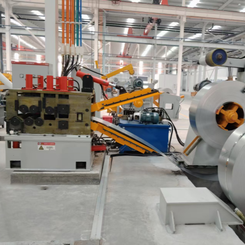
A steel coil decoiler is the first stage of a synchronized production line.
Its performance directly affects the operations that follow. Immediately after
the uncoiling stage, the metal strip enters a flattener or leveler to remove
coil set—the residual curvature left from storage. If the decoiler does not
provide stable, centered strip entry, the leveler will apply uneven pressure,
resulting in camber or twist in the strip.
In continuous welded pipe lines, the trailing end of one coil must be joined
to the leading end of the next. To avoid stopping the entire mill during
welding, an accumulator is positioned after the leveler. While the welding
machine joins the strips, the accumulator empties its stored material to feed
the continuous forming rolls. During this phase, the decoiler must stop
completely. Once the weld is complete, the decoiler must accelerate beyond the
nominal line speed to refill the accumulator while still meeting the current
consumption rate of the tube mill. SANSO designs these systems with coordinated
control panels that interface directly with the main line PLC, ensuring smooth
acceleration ramps and consistent strip tracking throughout the transition.
Maintenance Protocols for Structural Longevity
Preventive maintenance is necessary to sustain reliability and prevent
unplanned downtime on the factory floor. The main bearing of the spindle
operates under high radial loads. Greasing schedules must be followed
rigorously, using extreme-pressure (EP) lithium greases to prevent
metal-to-metal contact and premature wear.
Contaminants in the hydraulic oil can clog proportional valves, leading to
sluggish mandrel expansion or cylinder drift. Regular oil sampling and filter
replacements keep the hydraulic system operating at designed pressures.
Additionally, the slide ways for traveling coil cars and the linear guides for
sliding decoiler bases must be cleared of scale and lubricated. Wear on these
surfaces leads to misalignment, causing the strip to enter downstream machines
at an offset angle.
Frequently Asked Questions
Below are answers to common inquiries regarding the selection, operation, and
maintenance of industrial uncoiling equipment.
Q1: What are the main benefits of a double-mandrel decoiler over a
single-mandrel design?
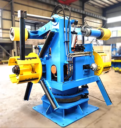
A1: A double-mandrel design features two spindles on a rotating base,
allowing an operator to load a new coil onto the idle spindle while the other
spindle actively feeds the mill. This configuration reduces changeover
stop-times to a fraction of the time required by single-mandrel systems, making
it highly suitable for high-speed continuous tube mills.
Q2: Why is a motorized uncoiler preferred over a pull-off model for
thin-gauge metal strips?
A2: Pull-off uncoilers rely on the downstream forming machine or leveler to
pull the material off the coil, which generates high tensile stress on the
strip. For thin-gauge metals, this tension can stretch the material, damage the
edges, or cause slippage. Motorized uncoilers actively feed the material,
keeping strip tension minimal and controlled.
Q3: How does a hydraulic snubber arm assist during the initial coil
threading process?
A3: The snubber arm uses a heavy-duty arm fitted with a motorized wheel to
apply downward pressure on the outside diameter of the coil. This prevents the
outer wraps from uncoiling when the steel bands are cut. Additionally, the
motorized wheel can rotate the coil slowly to feed the leading edge directly
into the entry table or leveler, reducing manual labor.
Q4: How do I select the proper mandrel expansion range for my
production line?
A4: Selection depends on the inner diameters (ID) of the coils provided by
your steel supplier. The most common standard IDs are 508 mm and 610 mm. The
mandrel must collapse below the minimum expected ID for easy loading and expand
securely beyond the maximum expected ID. For wider ranges, expansion segments or
bolt-on adapter shoes can be installed on the mandrel.
Q5: What causes uneven strip feeding, and how can it be
resolved?
A5: Uneven feeding is usually caused by centerline misalignment between the
decoiler mandrel and the entry guides of the leveler or forming mill. It can
also result from uneven expansion of the mandrel segments. Checking alignment
using optical or laser instruments and ensuring consistent hydraulic pressure to
the expansion cylinder can resolve this issue.
Product Inquiry and Consultation
Selecting the appropriate steel coil decoiler requires balancing load
capacities, material yield strengths, speed requirements, and line integration
details. SANSO designs and manufactures heavy-duty uncoiling machinery built to
withstand demanding industrial environments. For engineering specifications,
custom design options, or to discuss your production line requirements, please
contact our engineering team to submit a detailed inquiry.