In high-volume metal stamping, roll forming, and slitting operations, the raw
material delivery phase sets the operational limit for the entire production
line. Processing heavy metal coils requires continuous, controlled tension and
precise alignment to prevent material damage, equipment wear, and feed faults.
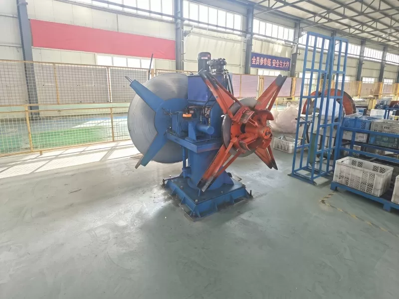
At the center of this initial stage is the steel coil uncoiler, a machine
engineered to hold, expand, and pay out coiled sheet metal with high
precision.
For manufacturing facilities operating press lines or roll forming machinery,
selecting the correct uncoiling equipment dictates the speed, safety, and
reliability of downstream processes. SANSO designs and manufactures heavy-duty
coil handling systems that directly address the mechanical stresses associated
with high-tensile materials and heavy coil weights.

The primary function of a steel coil uncoiler is to support the coiled metal
and rotate it at a controlled rate to match the speed of the straightener,
feeder, or forming machine. This operation requires a balanced combination of
structural strength and fine mechanical control.
Mandrel Expansion and Collapse Mechanisms
The core component holding the coil in place is the mandrel. To secure a
coil, the mandrel must enter the inside diameter of the coil in a collapsed
state and then expand outward to grip the inner wraps firmly. This expansion is
typically achieved using one of two mechanical designs:
Wedge-Type Expansion: This design utilizes a central
drawbar driven by a hydraulic cylinder. The drawbar pulls a series of sloped
wedges along matching ramps on the underside of the mandrel segments. As the
wedges slide, they force the outer segments outward in a uniform radial
direction. This configuration provides high clamping forces and excellent
concentricity, which helps minimize rotational vibration when handling heavy
loads.
Link-Type Expansion: This mechanism uses pivot links
connected to a central sliding collar. While simpler in construction, it is
generally reserved for lighter load capacities as the links experience higher
bending stresses compared to wedge-type systems.
Concentric expansion is necessary to avoid radial runout during rotation.
Even minor eccentricities in a rotating 15-ton coil can generate substantial
dynamic forces, leading to accelerated bearing wear and uneven payout
speeds.
Tension Control and Braking Systems
Controlling the tension of the strip as it leaves the coil is necessary to
prevent material sag and sudden jerks. Depending on the line configuration,
uncoilers use different braking and drive systems:
Pneumatic Disc Brakes: Commonly used in pull-off systems
where the downstream feeder pulls the material. The brake applies a constant
drag torque to prevent the coil from over-paying due to rotational inertia when
the line slows down or stops.
Variable Frequency Drive (VFD) Motors: In powered
configurations, an AC motor actively drives the spindle. The drive system
modulates the speed and torque of the motor based on feedback from loop sensors,
ensuring a continuous loop of material is maintained before entering the
straightener.
Regenerative Braking: For continuous, high-speed lines,
regenerative AC drives can act as brakes while generating electrical energy,
returning power to the factory grid and offering highly accurate tension
regulation.
Key Engineering Specifications and Structural Types
To match a steel coil uncoiler to a specific manufacturing process, engineers
must evaluate several distinct structural configurations and performance
parameters.
Single-Mandrel vs. Double-Mandrel Configurations
The choice between single and double-spindle machines is driven by production
volume and the frequency of coil changeovers.
Single-mandrel uncoilers are the standard choice for most medium-capacity
press lines. They feature one expanding spindle mounted on a heavy frame. While
cost-efficient and requiring a smaller floor footprint, the production line must
halt during coil loading, centering, and threading operations.
Double-mandrel (or rotary) uncoilers feature two separate spindles mounted on
a central rotating pedestal. While one spindle pays out material to the
production line, the operator can safely load and prepare the next coil on the
idle spindle. Once the active coil is fully depleted, the pedestal rotates 180
degrees, allowing the new coil to be aligned and threaded with minimal downtime.
This design is highly beneficial for continuous lines, such as high-speed tube
mills or high-volume stamping operations.
Load Capacity, Coil Width, and Outer Diameter Parameters
Sizing the machine requires a clear understanding of the physical dimensions
of the coils to be processed. The main structural specifications include:
Weight Capacity: Standard industrial classifications
typically range from light-duty (up to 3 tons), medium-duty (5 to 10 tons), to
heavy-duty systems (15 to 30 tons or more). The frame, spindle, and bearings
must be engineered to withstand both the static load and the dynamic forces
during acceleration and emergency stops.
Inside Diameter (ID) Range: Coils are wound on varying core
diameters, typically 508 mm (20 inches) or 610 mm (24 inches). The mandrel must
have an expansion range wide enough to securely grip both sizes, often achieved
through the use of bolt-on expansion shoe adapters.
Outside Diameter (OD) Capacity: The physical clearance
between the mandrel centerline and the machine base or floor determines the
maximum allowable coil diameter. Standard systems accommodate ODs from 1200 mm
up to 2000 mm.
Managing Material Defects and Processing Challenges
High-tensile steels and thick-gauge aluminum present unique material
behaviors during the uncoiling phase. Managing these characteristics prevents
strip damage and maintains feeding consistency.
Controlling Coil Set and Clock-Springing Effects
Coil set refers to the physical curvature retained by the sheet metal after
being tightly wound for storage and transport. When the outer band of a
high-strength coil is cut, the stored elastic energy can cause the outer wraps
to rapidly expand outward—a phenomenon known as clock-springing. This presents
serious safety concerns and can damage nearby equipment.
To prevent this, SANSO integrates heavy-duty pneumatic or hydraulic hold-down
arms. These arms feature a motorized roller that presses down on the outside
diameter of the coil, securing the outer wrap while the binding straps are
safely cut. The motorized roller then assists in threading the leading edge of
the material into the downstream straightener.
Seamless Integration with Straighteners and Feeder Systems
An uncoiler cannot completely eliminate coil set on its own. It must work in
tandem with a precision straightener or leveler. The uncoiler pays out the
material, while the straightener subjects the strip to alternating reverse bends
over a series of adjustable rollers, stretching the material past its yield
point to achieve flatness.
To prevent material marking and surface damage, particularly on polished
stainless steel or prepainted aluminum, the surface speed of the uncoiler must
match the inlet speed of the straightener. Any tension spikes can pull the
material too tightly over the straightener rollers, causing flat spots or
surface abrasion.
Operational Integration with SANSO Feeding Lines
Modern metal processing demands high levels of automation. Integrating the
steel coil uncoiler into a centralized control network is necessary to achieve
high throughput and protect the mechanical integrity of the machinery.
Automation and Loop Control Synchronization
A loop control system manages the speed differential between the continuous
payout of the uncoiler and the intermittent feed of the stamping press. When the
press cycles, it pulls material from a slack loop. The loop control system
monitors the depth of this loop and adjusts the uncoiler spindle speed
accordingly.
Several sensor options are utilized to monitor loop depth:
Photo-Electric Sensors: Multiple light beams are positioned
at different heights within the loop pit. As the material blocks or unblocks
these beams, the control system increases or decreases the VFD output.
Ultrasonic Sensors: Mounted above the loop, these sensors
measure the distance to the bottom of the loop continuously, allowing for
smooth, stepless speed adjustment of the spindle motor.
Mechanical Dancer Arms: A lightweight arm rides directly on
the material loop. The angular rotation of the arm shaft is measured by a
potentiometer to provide real-time speed control. This method is highly reliable
for thick, heavy-gauge materials that do not easily bend into a deep loop
pit.
Maintenance Protocols for High-Duty Cycle Operations
To maintain consistent operation, routine maintenance must be performed on
the mechanical and hydraulic systems of the uncoiler:
Wedge Slide Lubrication: The sliding surfaces of the
mandrel wedges experience high loads during expansion. They must be greased
regularly to prevent galling and ensure smooth expansion and contraction.
Bearing Inspection: Spindle bearings support heavy
cantilevered loads. Regular vibration analysis and temperature monitoring can
identify early fatigue before catastrophic bearing failure occurs.
Hydraulic System Maintenance: Hydraulic expansion systems
require clean oil to operate reliably. Proactive oil analysis, filter changes,
and pressure checks on the hydraulic power unit prevent pressure loss that could
cause the mandrel to contract during operation.
Brake Pad Replacement: For tension-controlled systems
relying on pneumatic brakes, brake pad wear must be monitored regularly. Worn
pads result in inconsistent tension control, leading to loop fluctuations and
potential strip buckling.
Selecting the Right Equipment for Your Production Line
Choosing the correct uncoiling configuration requires a thorough analysis of
your material specifications, production speeds, and floor space constraints.
Investing in a system with insufficient structural capacity leads to premature
wear, frequent maintenance shutdowns, and safety hazards on the production
floor. Conversely, an oversized system can result in unnecessary capital
expenditure and higher energy consumption.
Engineering teams must evaluate not only the current production requirements
but also potential future material specifications, such as transitioning to
higher-strength steel grades which demand higher back-tension and robust
hold-down mechanisms. SANSO engineers provide detailed technical assessments to
ensure that the structural frame, mandrel expansion range, and drive systems are
precisely configured to integrate with your existing roll forming, slitting, or
stamping lines.
Frequently Asked Questions
Q1: What is the main difference between a motorized and a
non-motorized steel coil uncoiler?
A1: A motorized uncoiler uses an AC or DC motor to actively turn the spindle
and pay out the material, regulated by a loop control system. This is suitable
for thin, sensitive materials or heavy coils where the downstream feeder cannot
pull the weight without slipping. A non-motorized uncoiler relies on the
downstream machine (such as a straightener or feeder) to pull the material off
the coil, utilizing a braking system to maintain tension and prevent
over-spooling.
Q2: How does a coil loading car improve safety and
efficiency?
A2: A coil loading car is a hydraulic lift table mounted on tracks that
positions and raises a heavy metal coil onto the mandrel shaft. This eliminates
the need for overhead cranes to align the coil directly onto the spindle,
reducing the risk of damaging the mandrel shaft and significantly decreasing
changeover times.
Q3: Can a standard mandrel handle coils with different inner
diameters?
A3: Yes, within a certain range. Standard mandrels have a limited expansion
stroke (e.g., 470 mm to 520 mm). To handle coils with much larger inner
diameters, such as 610 mm, operators attach expansion shoes or segments to the
mandrel plates, effectively increasing the starting diameter of the mandrel.
Q4: Why is a hold-down arm necessary for processing high-strength
steel?
A4: High-strength steel has high elastic memory. When the strapping bands
securing the coil are cut, the material tends to spring back violently. A
hold-down arm applies continuous pneumatic or hydraulic pressure to the outer
surface of the coil, holding it in place during band cutting and guiding the
leading edge safely into the feeding line.
Q5: How does mandrel eccentricity affect the manufacturing
process?
A5: If the mandrel does not expand concentrically, the coil will rotate
eccentrically. This creates an uneven payout speed and tension spikes, which can
cause material slippage in the feeder, incorrect feed lengths, accelerated wear
on the spindle bearings, and physical marking on the sheet metal surface.
Direct Consultation and Engineering Support
If you are looking to integrate a robust, industrial-grade steel coil
uncoiler into your press feeding or roll forming line, contact the engineering
team at SANSO. We provide technical verification, structural customization, and
complete line integration services to help you achieve consistent feed accuracy
and reliable daily operation. Send us your material specifications, coil
weights, and line layout requirements to receive a detailed technical proposal
and quotation.