In high-frequency welded tube and pipe production, the stability of the unwinding process directly determines the quality of the final weld seam and the geometric consistency of the product. A steel coil decoiler is not merely a rotating stand; it is a precision instrument that manages strip tension, coil alignment, and material flow into the forming section. With line speeds often exceeding 100 m/min and coil weights reaching 30 metric tons, any deviation in decoiling translates into edge waves, camber, or welding defects. This technical article examines the mechanical architecture, selection parameters, operational pain points, and integration strategies for modern decoilers, drawing on field data and engineering best practices.
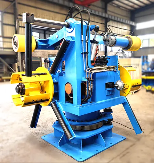
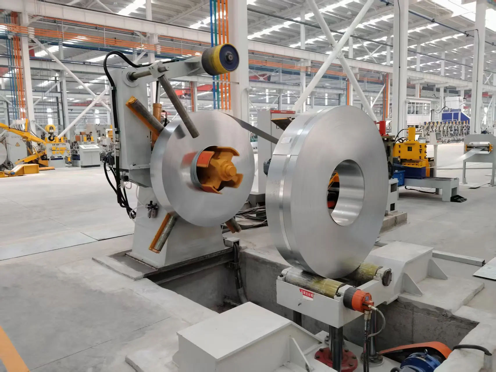
A robust steel coil decoiler performs four essential tasks: coil loading and centering, controlled unwinding via braking or driven systems, strip edge guiding (optional but critical), and coil end preparation for downstream joining. The typical machine comprises the following subsystems:
Expanding Mandrel: Hydraulic or mechanical segments that grip the coil inner diameter (typically 508 mm or 610 mm). Hydraulic expansion offers repeatable concentricity within ±0.5 mm.
Coil Car & Loading Arm: Hydraulically operated for safe coil transfer from storage saddles to the mandrel. Reduces operator intervention.
Drag Braking System: Pneumatic or hydraulic caliper brakes acting on the mandrel shaft to maintain back tension. Modern units feature proportional tension control.
Strip Alignment Unit (EPC): Edge position control with photoelectric sensors to correct lateral wandering, crucial for slit coils.
Hold-Down Roller & Peeler: Assists in initial coil threading and prevents free loop formation during acceleration/deceleration.
Each component must withstand cyclic loads from stop-start operations typical of tube mill changeovers. For high-strength steels (DP600, HSLA), a driven decoiler with an AC vector motor is preferred to maintain constant tension without friction-induced marking.
Selecting the correct steel coil decoiler requires evaluating five primary parameters. Mismatches often lead to strip breaks or poor loop control. Below is a technical checklist used by mill engineers:
Coil ID: Standard range 450–610 mm (customizable to 750 mm for large OD coils).
Coil OD: Up to 2,000 mm, influencing mandrel travel and overhead crane clearance.
Coil Width: 150 mm to 1,600 mm (narrow strips require segmented mandrel liners).
Coil Weight: 5–30 metric tons; heavy-duty decoilers employ dual-support bearing stands.
Hot-rolled (black) coils: require higher breakaway torque due to scale friction.
Cold-rolled and galvanized: demand soft contact surfaces (polyurethane-lined hold-down rolls).
Stainless steel: needs non-marking mandrel segments and controlled tension to avoid coil set.
Typical tube mill speeds: 30–120 m/min. High-speed mills (150+ m/min) need a dancer arm or loop pit to decouple decoiler inertia from forming section.
Acceleration rate: 0.5–1.5 m/s²; brake sizing must absorb regenerative energy.
Many mills now specify a steel coil decoiler with an integrated loop control system that adjusts braking torque based on real-time strip demand. This reduces tension spikes by 60% compared to fixed mechanical brakes, according to a 2023 study on tube mill efficiency.
Despite its simple appearance, decoiler-related issues account for nearly 23% of unplanned downtime in tube forming lines. Below are four frequent failure modes and field-proven remedies.
Slit coils often leave micro-burrs that dig into mandrel expansion plates, causing uneven gripping and oval coil deformation. Solution: Install replaceable tungsten carbide wear strips on the mandrel surface. For high-volume mills, SANSO offers a segmented mandrel with hardened steel inserts and a quick-change design, reducing maintenance downtime by 40%.
Inconsistent back tension causes the strip to flutter before entering the forming rolls, producing a “whip” that destabilizes the weld box. Solution: Replace passive mechanical brakes with a closed-loop tension control system using a load cell feedback. A modern steel coil decoiler equipped with an AC vector drive maintains tension accuracy within ±2% of setpoint.
Poorly wound coils (loose layers) telescope outward, rubbing against the decoiler frame and damaging strip edges. Solution: Integrate a hydraulic coil pusher and a vertical guide roller system that applies light side pressure. Pre-alignment with an EPC sensor before threading can reduce telescoping events by 80%.
Manual centering and threading can take 10–15 minutes per coil. Solution: Automated coil loading with a double-cone uncoiler design or a reel bar system. SANSO’s automatic decoiling stations feature a servo-driven coil car and hydraulic mandrel expansion, enabling changeovers under three minutes for coils up to 20 tons.
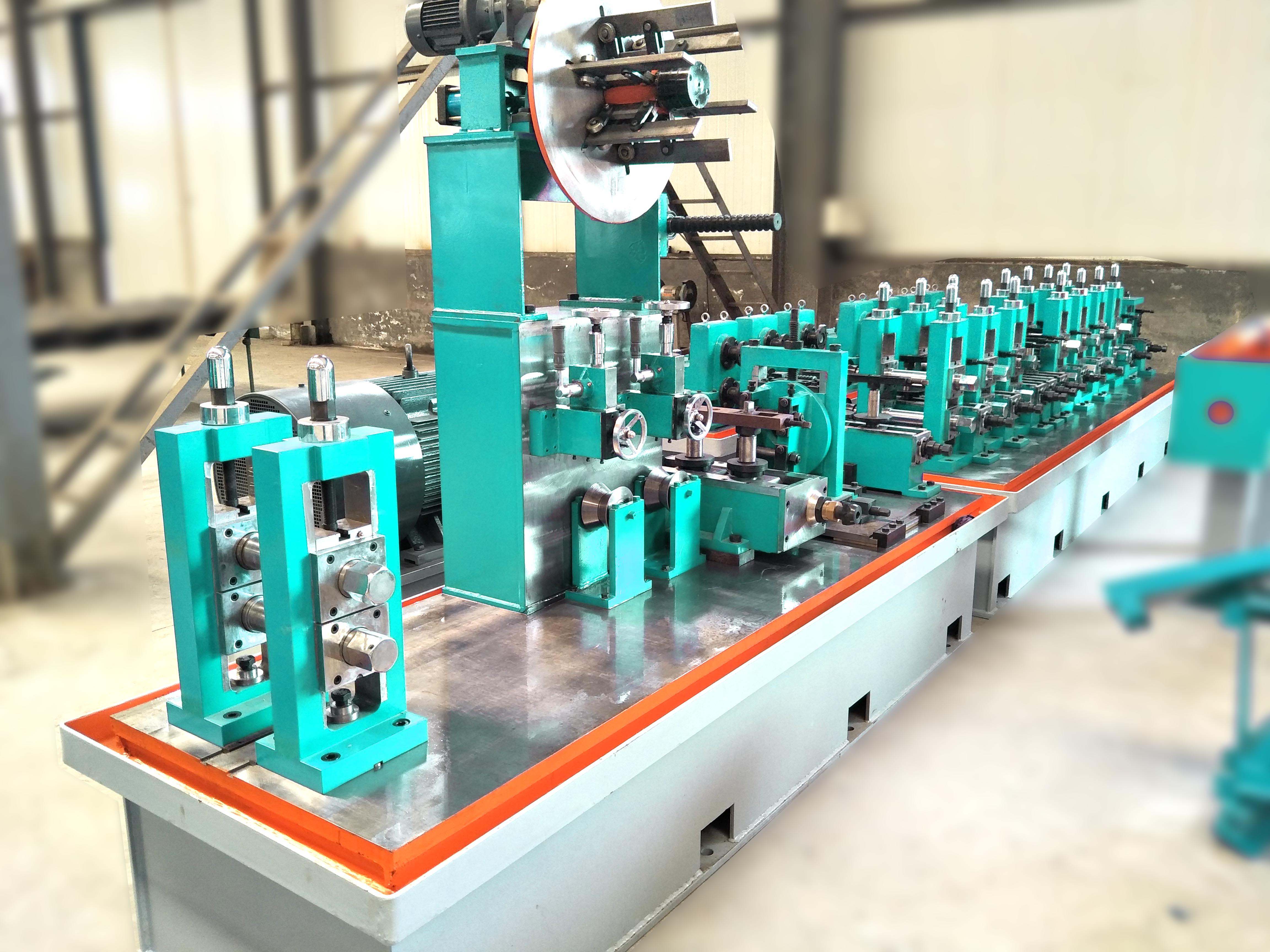
The steel coil decoiler does not operate in isolation; it is the first element of a synchronized material handling chain: decoiler → pinch leveler → strip accumulator → shear welder → forming section. Any eccentricity or tension disturbance from the decoiler propagates through the accumulator and directly affects the weld seam’s high-frequency heating pattern. For ERW tube mills, a variation of just 5% in strip edge alignment increases weld flash variability by 12–15%, leading to reject rates.
To achieve stable weld penetration, mill designers now specify decoilers with an active dancer arm that provides a “buffer zone.” The dancer position modulates the decoiler drive or brake, decoupling the inertial mass of the coil from the fast-responding forming rolls. In one case study involving a 2.5-inch pipe mill, retrofitting a dancer-controlled steel coil decoiler reduced weld seam hardness fluctuations from ±18 HV to ±6 HV.
Furthermore, the decoiler’s foundation rigidity matters. A deflection of 0.2 mm under full coil load can tilt the mandrel axis, causing the strip to enter the leveler at an angle. Mill builders recommend a reinforced concrete base with embedded anchor bolts, plus vibration-damping pads, to maintain geometric alignment over years of service.
Regular preventive maintenance on the steel coil decoiler extends bearing life and prevents sudden failures. The following checklist is based on ISO 16092-4 (safety requirements for coil processing lines):
Weekly: Inspect brake pads for wear (minimum thickness 6 mm). Clean mandrel sliding surfaces and re-grease expansion mechanism.
Monthly: Verify EPC sensor calibration using a reference edge. Check hydraulic hoses for leaks or chafing.
Quarterly: Measure mandrel radial runout with a dial indicator (limit ≤ 0.3 mm). Tighten all foundation bolts.
Annually: Perform nondestructive testing (dye penetrant) on the mandrel shaft and coil car pivot pins. Replace any bearings showing acoustic emission spikes.
From a safety perspective, all decoilers must include a locking pin for the expanding mandrel during maintenance, plus a light curtain or pull-cord switch along the strip path. SANSO uncoilers are designed with CE-compliant guarding and emergency stop loops that simultaneously halt the mill and apply the decoiler brake.
Investing in a high-rigidity steel coil decoiler with active tension control and automated centering delivers measurable returns: less scrap from edge damage, longer roll life in the forming section, and higher OEE through faster changeovers. For existing mills, retrofitting a dancer arm or replacing fixed brakes with proportional valve-controlled calipers can increase line uptime by 15–20% within six months. As tube mills push toward Industry 4.0, the decoiler becomes a data node—providing coil ID tracking, tension histograms, and predictive wear analytics. Selecting a partner like SANSO ensures that your decoiling system is engineered for both current steel grades and future automation demands.
A1: Heavy-duty steel coil decoiler systems for tube mills typically handle coil weights from 10 to 30 metric tons. For large-diameter pipe mills (OD > 16 inches), capacities can reach 40 tons. Selection depends on the mill’s monthly throughput and coil sourcing (domestic coils often lighter than imported ones). Always include a 20% safety margin above maximum coil weight to accommodate hydraulic shocks.
A2: Install hardened steel liners or replaceable carbide strips on the mandrel expansion segments. Another solution is to specify a slit coil edge conditioning station (deburring unit) before the decoiler. Regular inspection and polishing of mandrel surfaces every 2,000 operating hours also reduce burr-related wear. Some manufacturers, including SANSO, offer mandrels with induction-hardened surfaces (HRC 55-60) that resist micro-cutting.
A3: A motorized decoiler uses an AC or DC motor in regenerative mode to actively pull the strip back, creating tension. This provides precise control (±1%) and energy recovery but has higher upfront cost. A mechanical brake system applies friction to the mandrel shaft—simpler and cheaper, but tension accuracy is ±10-15% and brakes overheat during long, slow runs. For high-strength steels or lines >80 m/min, a motorized steel coil decoiler is recommended.
A4: Yes, but adjustments are required. Hot-rolled coils have a rough, scaled surface that increases friction against the mandrel; you may need higher hydraulic expansion pressure. Cold-rolled and galvanized coils are slippery—use polyurethane-lined hold-down rolls to prevent slippage. Also, the braking curve should be recalibrated because cold-rolled strip requires lower tension to avoid stretching. A modern decoiler with a programmable logic controller (PLC) can store recipes for different materials.
A5: Mandrel segments should undergo visual inspection every 1,500 operating hours or every three months. Measure the wear of sliding surfaces; if the gap between segments exceeds 1.5 mm, replacement is necessary. For high-utilization mills (three shifts, six days a week), segment replacement is typically scheduled every 12–18 months. Using wear sensors embedded in the mandrel can provide predictive alerts, minimizing unplanned downtime.
A6: Use a laser alignment tool to check parallelism between the decoiler mandrel axis and the pinch roll entry face. The vertical and horizontal offset should not exceed 0.3 mm per meter of distance. Additionally, install a steerable guide roller just after the decoiler to fine-tune strip entry angle. Failure to align precisely results in cambered strip and uneven edge wave patterns.
A7: No, a loop pit or dancer reduces tension sensitivity but does not replace the decoiler’s braking system. The decoiler must still provide controlled pay-off to maintain the loop’s fill level. In fact, a dancer-equipped line requires a responsive decoiler brake (or drive) to prevent loop bottoming or overflowing. Many engineers pair a dancer with an actively controlled decoiler for best results.