In the production of welded tube and pipe, the quality of the incoming strip directly determines weld integrity, dimensional consistency, and downstream forming stability. At the heart of this preprocessing stage lies the steel coil cutting machine—a system that transforms master coils into precision strips or blanks. Unlike generic slitting lines, equipment intended for high-frequency (HF) or laser welded tube mills must address narrow width tolerances, minimal burr formation, and consistent edge geometry. This article provides a technical deep dive into the specifications, mechanical adjustments, material considerations, and automation strategies that define industrial-grade coil cutting solutions, with direct reference to SANSO engineered systems.

A tube mill line begins with uncoiling, but the cutting stage is where feedstock geometry is finalized. The steel coil cutting machine performs either longitudinal slitting (dividing wide coil into multiple narrow strips) or cross-cutting (cut-to-length for plate edges). Key integration points:
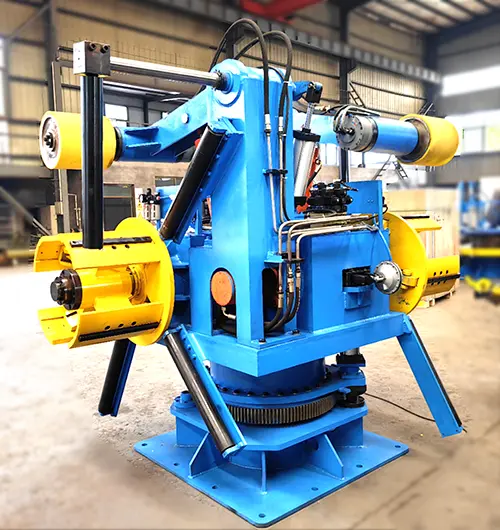
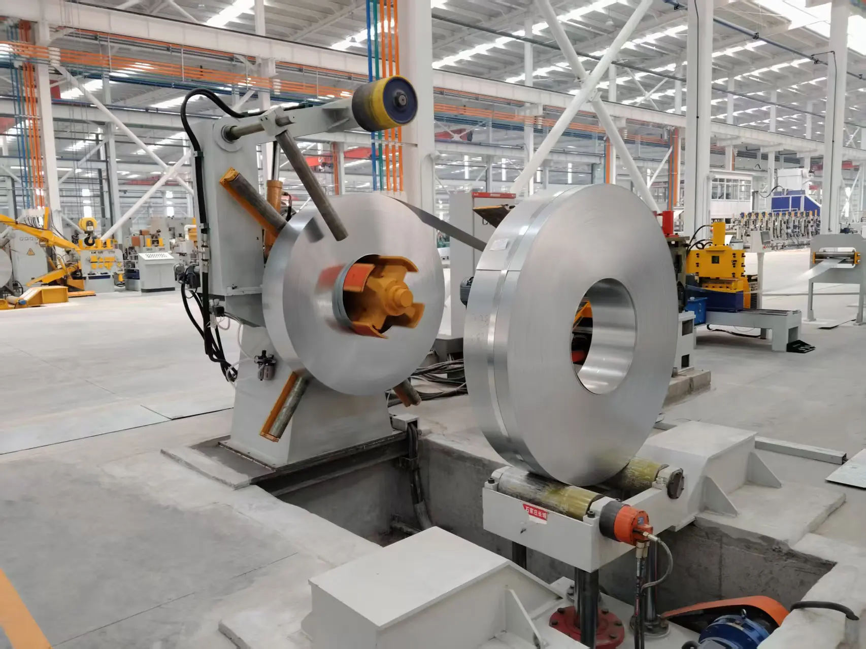
Input section: Heavy-duty uncoiler with hydraulic expansion mandrel and braking system.
Straightening leveler: Multi-roller assembly to remove coil set and crossbow.
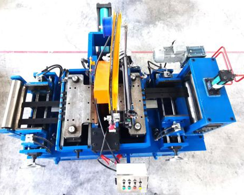
Slitter head: Arbor-mounted circular blades for precision shearing.
Recoiler/scrap winder: Tension-controlled coiling of slit strands or edge trim collection.
For welded tube applications, strip edge burr must not exceed 5% of material thickness; otherwise, high-frequency currents scatter, causing weld porosity. A properly configured steel coil cutting machine maintains burr heights ≤0.04mm for 2mm mild steel—a benchmark achievable only with rigid arbor support and backlash-free blade positioning.
Engineers evaluating coil cutting equipment must examine five interdependent mechanical variables. Below is the technical matrix used by SANSO during system design.
Arbor Runout (TIR): ≤0.01mm for 150mm diameter shafts. Excessive runout leads to cyclical blade contact, producing chatter marks on strip edges.
Blade Clearance (Side Gap): Typically 5-10% of strip thickness for carbon steel. High-strength steels (HSLA) require 12-15% clearance to prevent micro-cracking.
Overlap (Blade Penetration): 0.3-0.8mm depending on material yield strength. Overlap too low causes partial fracture; overlap too high accelerates edge work hardening.
Strip Tension Control: Tension range 4-12 kN/m² width. Closed-loop load cells adjust braking torque to prevent strip wandering and camber.
Straightening Roller Configuration: 7-9 work rollers top and bottom, with adjustable pitch for materials from 0.5mm to 8.0mm thickness.
Data from production environments shows that maintaining these parameters within ±2% tolerance reduces strip edge camber by 60% and improves downstream tube roundness by 35%.
Even with quality equipment, tube mills face recurring issues specific to coil cutting. Below are field-validated solutions.
Root cause: Worn or poorly aligned circular blades, uneven arbor deflection. Solution: Implement micrometer-adjustable blade spacers and hydraulically preloaded arbor bearings. SANSO systems feature a servo-driven clearance adjustment that compensates for thermal expansion in real time.
Root cause: Differential tension across strip width or mismatched roller leveling. Solution: Deploy a multi-roller leveler with individually adjustable backup rolls, plus a edge-trimming station before slitting to remove stress-relieved edges.
Root cause: Standard D2 tool steel lacks fracture toughness for tensile strengths >800MPa. Solution: Specify powder metallurgy (PM) or carbide-tipped blades with negative rake angle. Additionally, reduce line speed by 30-40% for AHSS to limit shock loading.
Root cause: Low exit tension or narrow guide chutes. Solution: Install a scrap chopper that cuts trims into 50-80mm lengths, paired with a pneumatic extraction system. This prevents jams that can damage the steel coil cutting machine arbor.
Root cause: Manual repositioning of blade spacers takes 90-120 minutes. Solution: Semi-automatic cassette slitter with quick-lock arbor design reduces changeover to under 20 minutes. Linear positioning sensors provide digital readouts for repeatable setups.
Modern tube mills must handle a portfolio of materials. The steel coil cutting machine requires distinct parameter profiles. The table summarizes recommended settings.
| Material Grade | Thickness Range (mm) | Blade Clearance (% of thickness) | Line Speed (m/min) | Blade Material |
|---|---|---|---|---|
| Mild steel (S235JR) | 0.8–4.0 | 6% | 80–120 | HSS M2 |
| HSLA (S500MC) | 1.5–6.0 | 10% | 40–70 | PM M4 |
| Stainless (304/316) | 0.5–3.0 | 8% | 30–50 | Carbide-tipped |
| DP980 (AHSS) | 1.0–2.5 | 14% | 15–25 | Carbide T10 |
Note that for DP980, preheating the strip edge to 50-60°C using induction prior to slitting reduces micro-crack risk by 70%.
To meet ISO 9001:2021 tube standards, modern coil cutting lines incorporate sensor-driven adjustments:
Laser edge scanners: Measure burr height and camber in real time at 2000 Hz. Data adjusts blade clearance via servo-actuated gearboxes.
Tension optimizer: PLC reads bridle roll currents and dancer arm position to maintain setpoint ±1.5% despite coil diameter variation.
Predictive blade wear model: Counts linear meters cut per material type and recommends regrind cycles. This avoids unplanned downtime.
MES connectivity: Production parameters (strip width, slitting pattern, batch ID) downloaded directly from ERP, eliminating manual entry errors.
SANSO integrates these features into its cutting line controllers, providing tube manufacturers with full traceability for each slit coil used in welded pipe orders.
Industrial steel coil cutting machines operate in high-contamination environments (metal dust, coolants). Key construction choices that extend Mean Time Between Failures (MTBF):
Cast iron slitter housings: Absorbs vibration and maintains alignment even after 10,000 operating hours. Fabricated steel frames drift 0.2mm after 18 months.
Labyrinth seals on arbor bearings: Prevent fine ferrous particles from migrating into bearing races. Typical sealed bearings fail after 6 months in slitting lines; labyrinth + purge air extends life to 36 months.
Quick-lock arbor nuts: Tool-less blade locking using hydraulic pressure (200 bar). Reduces operator fatigue and eliminates thread damage.
Modular scrap conveyor: Pinch-free design with replaceable wear plates. A central hinged section allows access for trim removal without unbolting guards.
Three common line configurations exist. Match based on weekly production volume and product mix.
Entry-level single-arbor slitter: Maximum 5 slit strands, manual blade adjustment. Suitable for job shops with <200 tons/week and 3-5 width changes daily.
Duplex (twin-arbor) slitter: Two independent cutting heads for staggered slitting – reduces arbor deflection and allows slit widths as narrow as 25mm. Ideal for automotive tube lines.
Turret-style rack slitter: Pre-loaded blade cassettes for 6-8 preset patterns. Changeover under 3 minutes. Recommended for high-mix, high-volume tube producers with >50 SKUs per shift.
For new tube mill projects, SANSO offers a line simulation service that calculates optimal slitting patterns and speed profiles based on your coil inventory and weekly order book.
Q1: What is the acceptable burr height on a steel coil cutting
machine for high-frequency welding?
A1: For tube
diameters below 100mm, the maximum burr is 0.05mm on either edge. Larger tubes
(100-300mm) allow up to 0.10mm, but any burr above 0.15mm causes weld arc
deflection. Use a side trimmer with overlapping blades set to 8% of thickness to
achieve consistent burr below 0.05mm.
Q2: How often should slitter blades be reground when processing HSLA
or stainless steel?
A2: For HSLA (yield strength
500-700 MPa), regrind after every 15,000-20,000 linear meters. For 304
stainless, shorten to 8,000-12,000 meters. Monitor cut edge quality – when burr
exceeds 0.08mm or 15% of thickness, schedule regrind. Avoid using blades beyond
0.15mm of radial wear, as this risks arbor damage.
Q3: Can a steel coil cutting machine handle aluminum coils for brazed
tube production?
A3: Yes, but requires
modifications: non-ferrous-specific blade clearance (3-5% of thickness),
polished blade surfaces to prevent galling, and an oil mist lubrication system
to avoid aluminum pickup. Standard steel slitting clearances will produce
rolled-over edges unsuitable for brazing.
Q4: What is the most common cause of strip camber after slitting, and
how to correct it?
A4: Incorrect tension profile
across the strip width – higher tension on one side stretches the edge unevenly.
Solution: calibrate the uncoiler brake torque and edge trim tension.
Additionally, inspect leveler roller parallelism; a 0.05mm skew over 1m width
induces 4mm/m camber. Use a laser alignment tool quarterly.
Q5: Does the steel coil cutting machine affect the tube mill’s energy
consumption?
A5: Indirectly, yes. Poorly slit
strips with high edge burr increase forming resistance by 15-20% at the fin pass
section, raising motor load. Also, inaccurate width tolerance (±0.5mm instead of
±0.1mm) causes excessive squeeze roll pressure, wasting hydraulic power.
Maintaining slitter accuracy reduces tube mill power consumption by roughly
8-12%.
Q6: What safety standards apply to coil cutting machines in tube
mills?
A6: ISO 16092-3:2019 (press brakes and
shears) covers guarding and two-hand controls. Also EN 746-2 for thermal hazards
if induction preheating is used. For automated lines, the ANSI B11.18 standard
ensures safe coil feeding. Ensure your machine includes light curtains at the
slitter entry and emergency pull cords along the recoiler.
Q7: How to validate the straightness of slit strip without stopping
production?
A7: Install a non-contact laser line
sensor array after the slitter. Three sensors spaced 300mm apart measure edge
profile. Any deviation >0.3mm/m triggers an alarm. This allows real-time
feedback to the leveler’s electric screw actuators, automatically correcting
strip bow.
Every tube line has unique requirements – from slit edge tolerances to material transition frequency. SANSO provides complete process engineering, from arbor design to automation integration, backed by field service support. Send your production parameters (material grades, thickness range, weekly tonnage, and target slit edge quality) to receive a technical proposal and line layout drawing.
Contact our engineering team now for a consultation:
Email: info@sansohftubemill.com
Online inquiry form: https://www.sansotubemill.com/contact.html
Request a quote
or a virtual line simulation report – response within 24 business hours.