In the demanding world of industrial tube production, the performance of a
pipe tube mill directly
determines product consistency, material yield, and production uptime. Whether
you manufacture line pipes for oil and gas, structural hollow sections, or
precision mechanical tubing, the mill’s design—from forming stations to welding
boxes and sizing sections—must balance rigidity with flexibility. This article
provides an in‑depth analysis of modern tube milling technology, focusing on
technical architectures, material behaviour, and process optimizations that meet
ASTM, API, and EN standards.
For over a decade, SANSO has supplied
heavy‑duty tube forming lines that integrate accumulator technology,
high‑frequency induction welders, and closed‑loop control systems. Their
approach eliminates common pitfalls such as seam deviation, edge wave, and
residual stress. Below we break down the core components, application‑specific
considerations, and strategies to elevate your tube mill efficiency.
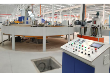
1. Core Architecture of a Modern Pipe Tube Mill
A complete tube production line includes several interdependent zones. Each
zone must be engineered to handle material grade, wall thickness, and final
diameter tolerances. Below are the essential stations in a high‑speed pipe tube mill:
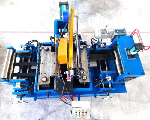
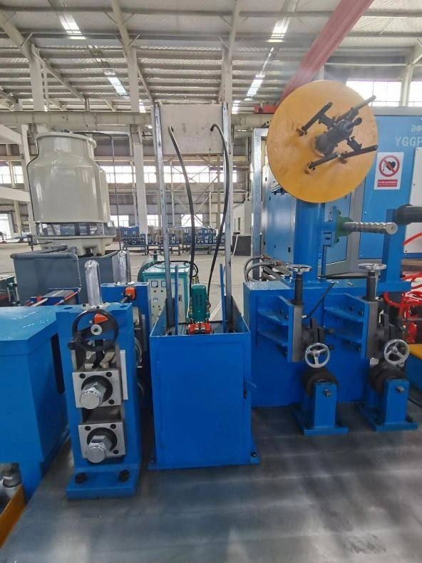
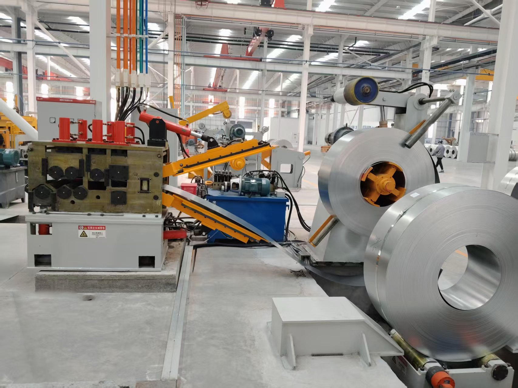
Uncoiler & Strip Preparation: Hydraulic expansion
mandrels, edge trimming, and strip guiding systems to ensure flat entry.
Accumulator (Looping Tower): Provides continuous operation
during coil splicing; reduces downtime and strip tension variation.
Forming Section (Breakdown & Fin Passes): Progressive
roll forming cages that gradually shape the flat strip into an open tube.
Welding Zone: High‑frequency induction (HFI) or solid‑state
HF contact welding; optional laser welding for stainless and exotic alloys.
Seam Annealing & Heat Treatment: Normalising the weld
zone to restore corrosion resistance and ductility.
Sizing & Straightening: Finishing stands to achieve
precise OD roundness and camber control.
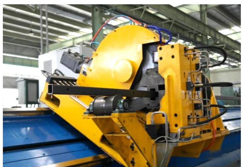
Cut‑off System: Flying saw or rotary shear for accurate
cut‑to‑length without stopping the line.
The integration of real‑time wall thickness monitoring and weld bead
inspection has become standard in contemporary mills. SANSO offers modular upgrades such as automatic weld
centering and strip edge positioning sensors, allowing mill operators to
maintain weld integrity at speeds exceeding 100 m/min.
2. Technical Deep Dive: Forming Forces, Springback & Weld Integrity
2.1 Roll Forming Mechanics & Material Considerations
When designing a pipe tube mill, engineers
must calculate the flower pattern—the progressive cross‑sectional deformation of
the strip. High‑strength low‑alloy (HSLA) steels and dual‑phase materials
exhibit increased springback, requiring over‑forming compensation. Finite
element analysis (FEA) is used to determine the exact number of forming passes
(typically 12 to 28) based on the ratio of tube diameter to wall thickness
(D/t). A D/t ratio below 15 demands more passes to avoid edge buckling and
corner wrinkling.
Additionally, strip width tolerance directly influences forming stability.
Even ±0.5 mm variation can cause uneven weld compression. Modern mills
incorporate servo‑driven side roll adjustments that automatically correct for
incoming strip deviations. This level of control also reduces roll wear,
lowering maintenance frequency.
2.2 High‑Frequency Welding Parameters & Defect Prevention
The weld zone is the most critical section of any tube mill. High‑frequency
welding (100–500 kHz) uses a V‑shaped convergence angle to concentrate current
along the strip edges. Key variables include:
Impedor design & position: Affects heating uniformity
and weld speed limits.
Squeeze roll pressure & geometry: Must produce an upset
bead without excessive thinning.
Heat input control: Prevents under‑welding (cold lap) or
over‑welding (burn‑through).
For critical applications such as boiler tubes or automotive structural
parts, many mill operators pair their line with online eddy current testing
(ECT) and ultrasonic inspection (UT). Data from these sensors can be looped back
to adjust weld power or roll positioning in milliseconds.
3. Industry‑Specific Solutions & Pain Points
Different end‑user segments impose unique constraints on tube mill design.
Below we address three common scenarios and how advanced pipe tube mill configurations resolve them.
Oil & Gas Line Pipe (API 5L Grade X42–X80)
Pain point: High toughness and low hardness variation across
the weld seam. Many mills struggle with inconsistent heat‑affected zone (HAZ)
properties.
Solution: Integration of in‑line normalising
coils and post‑weld cooling rates that follow specified thermal cycles.
Automated weld data logging ensures traceability per API 5L.
Precision Stainless Steel Tubes (AISI 304/316L for Food &
Pharma)
Pain point: Oxidation and surface scratching during forming.
Traditional roll materials can leave marks.
Solution: Use of
hardened D2 or ceramic‑coated rolls combined with air‑knife strip cleaning.
Laser welding (without filler) produces a smooth bead, minimising subsequent
scarfing operations.
Structural Square & Rectangular Tubes (EN 10219, ASTM A500)
Pain point: Corner radius variation and twist after sizing.
Standard mills produce high residual torsion.
Solution: Multi‑pass Turk’s head sizing units and inline straightening blocks with
force‑feedback adjustment. This achieves corner radii within ±0.3 mm over 12‑m
lengths.
Addressing these pain points directly translates to lower rejection rates and
higher first‑pass yields. SANSO offers custom roll
tooling design and process simulation before mill commissioning, eliminating
guesswork for challenging profiles.
4. Key Performance Indicators & Operational Excellence
To benchmark a pipe tube mill,
manufacturers should monitor these metrics:
Line uptime (%): Goal >92% including coil jointing and
tool changes.
Scrap rate (welded seam & strip ends): Below 1.5% for
carbon steels, <2.5% for stainless.
Changeover time (diameter range): Modern mills with
quick‑change cartridges achieve under 45 minutes.
Energy consumption per ton (kWh/t): Lowered by
high‑efficiency induction generators and servo drives.
Mill automation platforms (PLC + HMI with MES connectivity) log these KPIs in
real time, enabling predictive maintenance. For instance, vibration sensors on
forming stands detect roll bearing degradation before it affects tube geometry.
Similarly, weld power trending can signal impedor wear, allowing replacement
during scheduled coil changes.
5. Future Trends: Digitalisation, Laser Welding & Lightweighting
The tube manufacturing industry is shifting toward data‑driven production
lines. Digital twins of the entire forming process allow engineers to simulate
roll adjustments and predict final tube ovality without stopping production.
Laser welding is gaining ground for thin‑wall tubes (0.5 – 3 mm) because it
produces narrow HAZ and eliminates scarfing debris. Meanwhile, automotive and
renewable energy sectors demand thinner but stronger tubes (e.g., 980 MPa grade
steels), which requires mills with higher forming forces and precise edge
preparation.
Additionally, sustainable manufacturing now drives mill design: recirculating
cooling systems, reduced lubricant mist collectors, and low‑noise roll stands
are becoming standard features. Many buyers also request energy‑efficient
induction welders that reduce CO₂ footprint per finished ton.
Frequently Asked Questions (FAQ) – Pipe Tube Mill Selection &
Operation
Q1: What is the typical wall thickness range for a high‑frequency pipe tube
mill?
A1: For carbon steel, high‑frequency mills can process wall
thicknesses from 0.5 mm up to 12.7 mm, depending on tube diameter. For diameters
under 60 mm, the maximum wall thickness is usually limited to 4 mm, while larger
diameter mills (up to 610 mm OD) can handle thicker walls. Using solid‑state
welders ensures stable heat input even near the upper thickness limit.
Q2: How often should forming rolls be replaced on a continuous pipe tube
mill?
A2: Roll life depends on material abrasiveness and
production volume. For mild steel, chrome‑plated rolls typically last
3,000–5,000 tons before re‑profiling. For galvanized or high‑silicon steel,
rolls may need replacement every 1,500–2,000 tons. Implementing automatic
lubrication and using tungsten‑carbide inserts on highly stressed passes can
extend roll life by 40%.
Q3: Can the same mill produce round, square, and rectangular tubes?
A3: Yes, if the mill is designed with a versatile forming
section and a quick‑change tooling system. Round‑to‑square production requires
additional sizing turks’ heads and dedicated fin passes. Many modern lines
include removable cassettes for round and shaped sections, reducing changeover
time to under two hours. However, for high‑volume dedicated profiles, a separate
line is more economical.
Q4: What welding method is best for stainless steel tube production?
A4: For austenitic stainless (304/316L), both HF welding and
laser welding are used. HF welding is cost‑effective for thicker walls (>1.5
mm) but requires careful scarfing and passivation. Laser welding produces a
flush bead with minimal oxidation, ideal for decorative or hygienic tubes. For
ferritic stainless, TIG welding is sometimes preferred to maintain ductility.
Always perform a corrosion test (ASTM A262) to validate weld quality.
Q5: How does an accumulator improve pipe tube mill efficiency?
A5: The accumulator stores a loop of strip material,
allowing the mill to continue running while a new coil is being prepared and
welded to the tail end of the previous coil. This eliminates line stops for coil
change, increasing overall uptime from ~75% to over 92%. It also reduces tension
peaks that could distort the strip before forming. Learn about accumulator integration
here.
Q6: What sensors are recommended for in‑line weld inspection?
A6: A combination of eddy current (ECT) for surface defects,
ultrasonic (UT) for internal flaws, and a weld bead camera for geometry. For API
lines, phased array UT is mandatory. The data should feed into a statistical
process control (SPC) dashboard, enabling immediate adjustments to weld power,
squeeze roll pressure, or strip alignment.
Need a Customised Pipe Tube Mill for Your Production
Targets?
Our engineering team provides complete line layouts, roll tooling design, and
remote commissioning support. Whether you require a compact mill for
small‑diameter precision tubes or a high‑tonnage line for structural profiles,
SANSO delivers mill solutions with documented
performance in Europe, Southeast Asia, and the Americas. Request a feasibility
study or a quotation today.
Direct inquiry: www.sansotubemill.com/contact
Email: info@sansohftubemill.com
Send us your tube specifications (material, OD range, wall thickness,
required output) and we will respond with a technical proposal within 48
hours.