In industrial tube manufacturing, the efficiency of the flying cut-off station directly dictates the overall output of the production line. Selecting the correct hss saw blade requires a balanced understanding of metallurgy, tooth geometry, coating characteristics, and the mechanical dynamics of the cutting system. As an established manufacturer of high-precision cold sawing equipment, SANSO maintains rigorous quality standards to ensure that sawing tools operate reliably under continuous production loads. This article provides a comprehensive evaluation of high-speed steel cutting tools, analyzing the mechanical and metallurgical factors that prevent premature failure and ensure clean, burr-free cuts.
The performance of a circular cold saw blade depends heavily on the chemical composition of its base material. High-speed steel (HSS) is favored for its high hardness, wear resistance, and toughness. The two most common alloy grades used in tube mill cut-off applications are M2 (DMo5) and M35 (Co5).
The M2 grade is the standard material for most carbon steel cutting applications. It contains approximately 6% tungsten, 5% molybdenum, 4% chromium, and 2% vanadium. The combination of these elements forms highly stable alloy carbides after heat treatment, which provides:
When processing harder materials such as stainless steels (e.g., AISI 304 or 316) or high-strength low-alloy (HSLA) steels, the standard M2 grade often experiences accelerated thermal degradation. In these scenarios, the M35 grade is utilized. This alloy incorporates 5% cobalt, which significantly alters its physical properties:
When examining high-speed steel metallurgy, the standard hss saw blade typically utilizes DMo5 for general structural tubing, whereas Co5 is reserved for high-tensile components or thick-walled pipes where heat generation is concentrated.
Untreated high-speed steel has limitations in heat dissipation and friction control. Applying a physical vapor deposition (PVD) coating to a hss saw blade modifies its surface hardness and thermal conductivity, protecting the base metal from premature wear.
TiN is a versatile, entry-level PVD coating distinguished by its gold color. With a surface hardness of approximately 2,300 Vickers (HV) and a maximum oxidation temperature of 600°C, TiN reduces the friction coefficient between the blade surface and the pipe wall. This coating is suitable for cutting soft carbon steels and structural tubes with light wall thicknesses.
TiCN provides a higher surface hardness (approx. 3,000 HV) and a lower coefficient of friction than TiN. The inclusion of carbon enhances the coating's resistance to abrasive wear. It is highly effective for processing high-strength structural carbon steels, although its oxidation temperature limit is slightly lower at 400°C, requiring constant flood cooling during operation.
For demanding cutting conditions, such as dry cutting or processing high-alloy steels, TiAlN is a preferred choice. Under high temperatures, the aluminum within the coating reacts with atmospheric oxygen to form a thin, protective layer of aluminum oxide. This passive layer acts as a thermal barrier, reflecting heat into the cut chips rather than the body of the blade. The surface hardness reaches 3,300 HV with an oxidation threshold of 800°C.
When cutting non-ferrous metals like copper, brass, or aluminum, standard titanium-based coatings can cause galling or material transfer. CrN offers excellent adhesion resistance, low residual stress, and a low friction coefficient, preventing workpiece material from welding onto the tooth flanks.
The efficiency of the cutting process depends heavily on the tooth geometry selected for the specific tube profile. Selecting an incorrect tooth pitch or angle leads to vibration, poor surface finish, and accelerated tooth wear.
There are two primary tooth profiles used in industrial tube cutting:
The choice of tooth pitch for a hss saw blade depends directly on the wall thickness of the pipe being cut. A fundamental rule of thumb in cold sawing is that at least three teeth must be in contact with the workpiece at all times. If the tooth pitch is too large, the teeth will straddle the pipe wall, leading to severe shock loads that will chip the cutting edges. Conversely, if the pitch is too fine, the gullets will fill with chips before the cut is completed, causing the blade to bind and crack.
The table below provides a general guide for selecting the appropriate tooth pitch based on tube wall thickness:
| Wall Thickness (mm) | Recommended Tooth Pitch (T / mm) | Tooth Profile Recommendation |
|---|---|---|
| 0.5 – 1.0 | 3 – 4 | Bw (Form B curved) |
| 1.0 – 2.0 | 4 – 5 | Bw (Form B curved) |
| 2.0 – 3.0 | 5 – 6 | Hz (Form C) or Bw |
| 3.0 – 5.0 | 6 – 8 | Hz (Form C) |
| > 5.0 | 8 – 12 | Hz (Form C) |
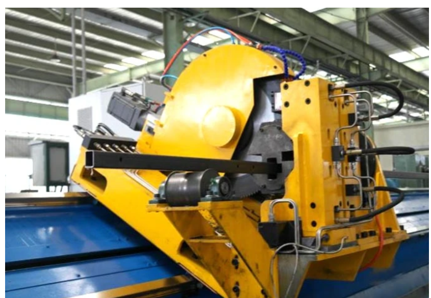
On high-speed tube welding lines, the cold saw must operate dynamically. The saw carriage must accelerate to match the speed of the continuously produced pipe, perform the cut, and return to its starting position. Any speed mismatch between the carriage and the pipe introduces severe lateral stress on the blade body.
By utilizing flying cut-off systems manufactured by SANSO, operators can achieve consistent feed speeds and precise synchronization, which reduces mechanical deflection. When the sawing head experiences vibration, the high-speed steel disk is subjected to bending moments that it is not designed to withstand. This deflection results in wavy cuts, excessive burr formation, and catastrophic blade failure.
To prevent these issues, operators must regularly monitor the following mechanical parameters:
The high friction generated during cold sawing requires adequate cooling to prevent structural damage to the tool. While the term cold sawing implies a low workpiece temperature, localized temperatures at the shear zone can exceed several hundred degrees Celsius.
Traditional flood cooling utilizes a soluble oil emulsion (typically 5% to 10% concentration) pumped directly onto the cutting zone. The liquid serves two purposes: it cools the blade body and workpiece, and it flushes the chips out of the tooth gullets. Proper positioning of the coolant nozzles is critical. One nozzle should point directly into the entry cut, while another should clear chips from the teeth as they exit the tube.
Many modern flying cold saws utilize MQL systems instead of flood cooling. These systems deliver a microscopic mist of high-performance biodegradable ester oil mixed with compressed air directly to the tooth edge. MQL operates on the principle of preventing heat generation through lubrication rather than cooling the tools after heat has built up. This approach reduces clean-up requirements and helps keep the plant environment cleaner, though it requires precise calibration to ensure the oil mist reaches the cutting zone consistently.
Understanding the wear patterns of high-speed steel circular saw blades is necessary for identifying machine calibration errors and optimizing tool life.
This is the normal, gradual wear of the tool material on the relief face. It occurs as a result of abrasive friction against the workpiece wall. Flank wear should progress uniformly across all teeth. When flank wear reaches approximately 0.2 mm to 0.3 mm, the blade should be removed and resharpened to prevent excessive heat buildup.
BUE occurs when the workpiece material becomes pressure-welded to the tooth rake and flank faces. It is common when cutting soft, ductile materials like low-carbon structural steel or stainless steel. BUE alters the tool geometry, increasing cutting forces and leading to micro-chipping. To address this issue, operators can increase the concentration of the cooling fluid or transition to a specialized PVD coating like CrN or AlTiN.
This wear pattern is characterized by small chips breaking off the cutting edge. It is typically caused by mechanical shocks, such as when the saw blade enters the tube wall too quickly, or when the pipe vibrates due to inadequate clamping. To resolve this, the feed rate during the entry phase should be reduced, and the clamping jaws should be inspected for wear.
When cracks develop starting from the bottom of the tooth gullet and propagate toward the center hole, it indicates severe thermal stress or excessive feed forces. This occurs when the tooth gullets become packed with chips that cannot escape, or if the blade is run with a dull cutting edge. Regular resharpening and verifying the correct tooth pitch for the pipe wall thickness can help prevent this failure mode.
In addition to monitoring tool wear, inspecting the cut quality of the tube provides valuable feedback regarding the state of the sawing system.
Q1: What is the main cause of premature teeth breakage on a hss saw blade?
A1: Premature teeth breakage is usually caused by mechanical shock, such as unstable tube clamping, backlash in the gearbox, or using a tooth pitch that is too large for the wall thickness of the pipe being cut. Ensuring that at least three teeth are continuously engaged in the cut helps distribute the mechanical load and reduces the risk of chipping.
Q2: How many times can a high-speed steel circular saw blade be resharpened?
A2: A standard blade can typically be resharpened between 10 and 20 times, depending on the severity of the wear or chipping. During resharpening, the original tooth profile and clearance angles must be maintained. If the blade has a PVD coating, it may need to be recoated after several sharpenings to maintain its original performance levels.
Q3: Why is stainless steel harder to cut with an HSS blade than carbon steel?
A3: Stainless steel has a high work-hardening rate and low thermal conductivity. When the blade contacts the material, the stainless steel quickly hardens at the shear zone, and the heat is transferred into the blade rather than the chips. To manage this, cobalt-alloyed blades (M35) with TiAlN coatings should be used at lower cutting speeds and higher feed rates.
Q4: How do I know when it is time to change the cold saw blade?
A4: Indications that a blade needs to be replaced include a noticeable increase in cutting noise, heavy burrs on the cut edges of the tube, a change in the color of the chips (indicating excessive heat), or visual wear on the tooth flanks exceeding 0.2 mm.
Q5: Can I run a cold saw blade without coolant?
A5: Running high-speed steel blades without lubrication is not recommended for tube mill applications. The high friction can lead to rapid heat buildup, thermal cracking, and catastrophic tool failure. If liquid coolant is not permissible, an MQL system should be used to provide localized lubrication to the cutting edge.
Achieving stable and reliable tube cut-off operations requires selecting the correct combination of steel grade, coating, and tooth geometry. When specifying your requirements, please provide detailed information regarding your tube mill's operating speed, the steel grades being processed, wall thicknesses, and the mechanical specifications of your flying cut-off carriage.
Please contact SANSO with your specific material grades and machine parameters. Our engineering team can provide technical support and custom recommendations to help you configure your cutting parameters for consistent production quality.