Continuous welded pipe manufacturing requires highly synchronized machinery to transform flat strip coils into finished cylindrical or structural profiles. The operational rhythm begins at the entry stage, where raw material must be fed into the forming mill with consistent alignment and tension. Setting up this initial phase incorrectly introduces geometric variations that propagate throughout the entire roll forming process. Utilizing a highly efficient uncoiler machine at the entry stage is foundational to maintaining strip control from the outset. This equipment supports heavy coils of sheet metal, expanding inside the inner core to grip the material securely while allowing controlled rotation during the feeding phase.
In high-capacity mills, equipment durability and operational reliability dictate overall productivity. The heavy-gauge coil handling systems designed by SANSO demonstrate how structural rigidity and precise tension control mitigate coil damage and feed line misalignment. Understanding the engineering parameters, mechanical configurations, and material handling physics of these machines allows manufacturing facilities to improve throughput and maintain tight tolerances on finished tube products.
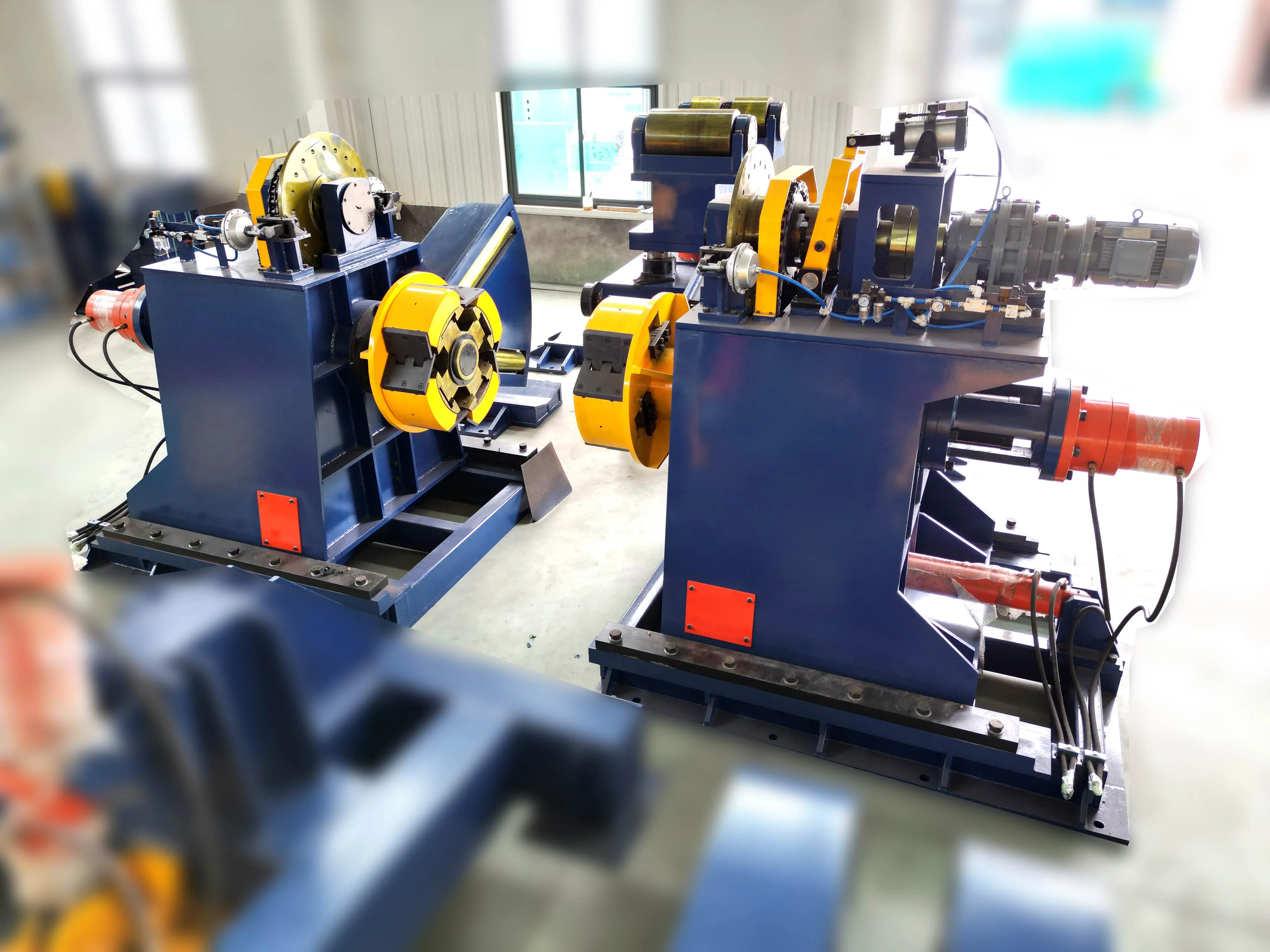
The core function of an uncoiler machine is to hold and feed the metal strip smoothly into the leveller or straightener before it enters the forming rolls. If the coil is allowed to rotate freely without controlled resistance, centrifugal forces and residual stresses can cause the outer wraps to loosen rapidly, leading to a phenomenon known as clock-springing. Conversely, excessive resistance can stretch narrow strips or cause slippage within the forming drive rollers. To prevent these issues, modern entry lines use heavy-duty shafts, robust bearings, and sophisticated braking systems.
The main spindle of the payoff reel is subject to substantial bending moments caused by the overhung load of the steel coil. For instance, a 15-metric-ton coil exerts significant downward force on the unsupported end of the mandrel. To withstand these forces without deflection, the shaft is forged from high-tensile alloy steel and supported by heavy-duty double-row spherical roller bearings. This structural rigidity minimizes shaft runout, ensuring that the coil remains perpendicular to the centerline of the forming mill during rotation.
Securing the coil onto the spindle requires a reliable expansion mechanism that matches the internal diameter of the coil. This is achieved through either hydraulic expansion or mechanical cone linkages. The choice between these two designs depends on the weight of the coils, the material thickness, and the frequency of changeovers.
Hydraulic Expansion: Uses a centralized hydraulic cylinder acting on wedge-shaped slides to push mandrel segments outward. This configuration provides uniform radial force along the entire inner circumference of the coil. It is the preferred method for heavy coils, as the hydraulic pressure actively holds the coil core against high torsional forces during acceleration and braking.
Mechanical Cone Expansion: Relies on manual or motorized screw jacks to move opposing cones into the coil ends. While suitable for lighter coils or narrower strip widths, mechanical systems may experience localized stress concentration at the coil edges, potentially deformation the inner wraps of thin-gauge materials.
Selecting an appropriate uncoiler machine depends heavily on the maximum coil weight, outer diameter, and the range of inner diameters required by the production schedule. Dual-cone configurations are often deployed for wide, heavy steel coils, whereas single-mandrel cantilevered designs are standard for medium-to-light duty pipe production lines where rapid side-loading is preferred.
| Parameter | Light-Duty Configuration | Heavy-Duty Configuration |
|---|---|---|
| Coil Weight Capacity | 1,500 kg to 5,000 kg | 10,000 kg to 25,000 kg |
| Expansion Range | 450 mm – 520 mm | 508 mm – 610 mm (with adapter shoes) |
| Braking System | Pneumatic Disc Brake | Hydraulic Multi-Disc / Regenerative AC Motor |
| Threading Drive | Manual or Auxiliary AC Motor | Fully Synchronized Variable Frequency Drive (VFD) |
During high-speed tube forming, several operational issues can arise at the entry section. Strip mistracking, where the metal drifts laterally away from the mill centerline, causes uneven stress distribution across the forming rolls, leading to twisted tubes or premature roll wear. This drift is often caused by non-parallel alignment between the uncoiler shaft and the first entry guide stand.
The engineering department at SANSO utilizes high-yield steel frames and precision machining to ensure that the base assembly of the payoff system remains aligned with the mill axis. To compensate for variations in coil winding quality, some advanced feed lines incorporate lateral shifting bases. These bases use hydraulic cylinders to slide the entire payoff assembly left or right along linear guide rails, guided by automatic edge-sensing sensors that actively detect strip position deviations in real-time.
Processing high-strength low-alloy (HSLA) steels or thick-walled carbon steels introduces significant mechanical resistance. When the steel banding securing a new coil is cut, the stored elastic energy in the outer wraps can cause violent unwinding. This poses safety hazards and risks damaging nearby sensor arrays or feeding guides.
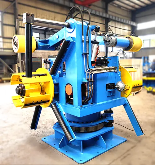
To safely manage high-strength coils, heavy-duty feed systems must be equipped with an overarm hold-down wheel, also known as a snubber arm. This hydraulic arm presses a heavy polyurethane-coated roller against the outer diameter of the coil, maintaining downward pressure while the steel bands are severed. Once the banding is removed, the hold-down wheel guides the leading edge of the strip into the peeler plate and pinch rolls, preventing the material from losing its coiled shape prematurely.
Minimizing changeover time is a major priority for high-efficiency tube production lines. The time spent crane-lifting a new coil, centering it on the mandrel, and manually threading the strip reduces the overall operational equipment effectiveness. An integrated coil loading car resolves this bottleneck by staging the next coil while the current one is still being processed.
The coil car features a V-shaped cradle mounted on a hydraulic scissor lift, traveling along floor rails perpendicular to the spindle axis. When the previous coil is finished, the empty mandrel collapses, the coil car moves the new coil into position, raises it to match the spindle centerline, and slides it onto the mandrel. This automated sequence reduces loading times from twenty minutes down to less than three minutes, protecting the mandrel segments from impact damage associated with overhead crane loading.
When configuring a heavy-duty uncoiler machine, engineers focus on coordinating the speeds of the payoff spindle and the pinch roll feeder. In passive payoff setups, the strip is pulled entirely by the forming mill or the leveler, with a pneumatic brake on the spindle providing the back-tension. In active payoff configurations, an AC variable frequency motor drives the spindle to feed the strip, synchronizing with a loop control sensor located in a pit downstream. This looping system prevents tension spikes from pulling the strip too tightly, protecting delicate thin-walled materials from stretching.
The operational stability of the uncoiler machine directly impacts the dimensional accuracy of the subsequent forming stages. Fluctuations in tension can lead to variations in the outer diameter of the welded tube, particularly during high-frequency induction welding where consistent weld-gap presentation is necessary. Consequently, integrating a loop control system with photoelectric sensors or ultrasonic transducers allows the drive motor to continuously adjust its rotation speed, maintaining a constant catenary loop before the strip enters the straightener.
Safety systems must also be deeply integrated into the mechanical design of the payoff line. Emergency stop sequences must halt the high-inertia rotation of a 20-ton coil almost instantaneously. This requires pneumatic caliper disc brakes or regenerative motor braking capable of absorbing large amounts of kinetic energy without fading. Furthermore, interlocking guard rails, pressure-sensitive mats, and light curtains prevent operators from approaching the rotating spindle or the hydraulic pinch rollers during automatic operation.
Selecting the correct model for a welded tube production facility requires analyzing several mechanical factors. Specifying a machine with insufficient load capacity can lead to fatigue failure of the main bearing housing, while an oversized system may lack the sensitivity required to process thin-walled materials without causing strip distortion. Plant engineers should evaluate the following structural specifications:
Maximum Coil Weight and Width: Determines the physical size of the spindle, bearing size, and base frame construction.
Material Yield Strength and Thickness Range: Dictates the required horsepower of the threading drive, the sizing of the hydraulic expansion cylinder, and the down-pressure of the snubber arm.
Line Speed Capability: Must match or exceed the maximum speed of the tube forming mill, typically ranging from 30 to 120 meters per minute.
Mandrel Expansion Style: Determined by whether the inner core diameters of incoming coils are uniform or vary across different steel suppliers.
Correct alignment between the coil processing equipment and the subsequent forming mill is necessary to prevent edge wave defects in the strip. Regular maintenance schedules should include ultrasonic testing of the mandrel shaft to detect micro-cracks, lubrication of the wedge slides to ensure uniform expansion, and inspection of brake pad wear to guarantee consistent holding tension during operation.
Industrial pipe manufacturers requiring stable, heavy-duty strip feeding solutions should evaluate how equipment configuration impacts production efficiency. Proper equipment specification prevents feed line deviations, minimizes material waste, and reduces mechanical downtime during coil changes. The engineering team at SANSO assists facilities globally by customizing payoff and coil handling lines to fit specific space limitations and material parameters.
To receive a tailored technical proposal and detailed schematic drawings for your specific tube mill line, please submit your manufacturing parameters, including maximum coil weight, strip width range, wall thickness limits, and material yield strengths, to our engineering division for a professional consultation.
A1: A single-mandrel machine features a cantilevered shaft supported on one side, which is ideal for standard production lines where lateral loading is fast and convenient. A double-mandrel system, or rotary turret uncoiler, features two separate spindles mounted on a rotating base. This allows the operator to load a new coil on one side while the other spindle is feeding the line, reducing coil changeover downtime in high-output plants.
A2: The loop control system uses ultrasonic or photoelectric sensors to measure the depth of the strip loop in a pit located between the payoff unit and the straightener. If the loop becomes too shallow, indicating high tension, the sensor signals the variable frequency drive (VFD) to speed up the mandrel rotation. If the loop becomes too deep, the drive slows down, maintaining a constant catenary loop that isolates the mill from tension variations.
A3: Hydraulic expansion provides uniform radial force along the inside diameter of the coil via a centralized wedge system powered by a hydraulic power unit. This ensures a more secure grip, which is necessary to prevent heavy coils from slipping under high braking torque. Manual mechanical expansion relies on screws or linkages that are difficult to tighten consistently on heavy loads and are more prone to mechanical wear over time.
A4: High-strength steel coils contain significant elastic spring-back energy. If the packaging bands are cut without restraint, the strip ends can whip outward violently. A hydraulic snubber arm presses a heavy roller against the outside diameter of the coil, securely holding the outer wraps down while the bands are cut, and then slowly rotates to feed the lead edge safely into the entry pinch rolls.
A5: Regular maintenance requires lubricating the internal sliding wedges of the mandrel to ensure complete and uniform expansion. Additionally, engineers must inspect the main shaft bearings for play, verify that the hydraulic cylinder rotary union is free of leaks, and check that the mounting bolts securing the machine base to the foundation remain torqued to specification to prevent lateral shifting.


