Continuous operation in welded tube production requires a reliable, uninterrupted flow of raw steel strip. When a coil runs out, the transition to the next coil presents a significant operational bottleneck. Standard manufacturing setups rely on entry equipment to handle this transition smoothly, utilizing a robust strip joiner to splice the tail end of the expiring coil to the leading edge of the new coil. Equipment designs manufactured by SANSO provide the continuous feed necessary to prevent downstream stoppage, directly protecting the forming, welding, and sizing sections of the tube mill from sudden thermal and mechanical shocks.
Implementing a dedicated strip-splicing system ensures that the roll forming mill runs continuously. Without this continuous feeding mechanism, operators must thread each new coil through the entire roll-forming line manually. This manual threading process causes extensive tool wear, increases scrap rates during startup, and results in substantial production downtime. Analyzing the mechanical components, operational steps, and integration factors of these systems helps manufacturers make informed capital decisions.
A reliable splice requires precise alignment, clean shearing, and consistent welding. The process begins when the tail end of the processed coil reaches the entry section. The operator stops the entry end of the line while the downstream tube mill continues to run on strip stored within a horizontal or vertical accumulator.
During this temporary pause, the operator relies on the strip joiner to perform clean, square cuts on both the trailing and leading edges of the steel. This sequence involves several coordinated steps:
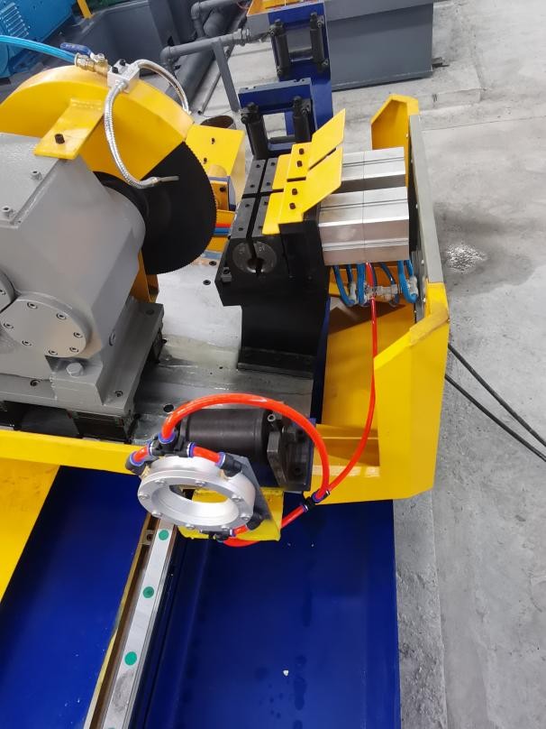
Clamping and Positioning: Heavy-duty pneumatic or hydraulic clamping plates hold both strip ends firmly in place. This prevents any lateral shifting or vertical bowing during shearing and welding operations.
Double-Cut Shearing: A hydraulic shear head trims both the trailing end of the old coil and the leading end of the new coil. Trimming both ends simultaneously or sequentially on a single machine ensures that the edges are perfectly parallel, leaving a uniform gap suitable for welding.
Transverse Alignment: Fine-tuning alignment guides allow operators to match the centerlines of the two coils. Proper centering prevents camber issues, which can cause the strip to drift as it enters the forming mill.
Automated Welding: A motorized weld torch carriage moves across the joint width. Depending on the material thickness and grade, the process may utilize Tungsten Inert Gas (TIG), Metal Inert Gas (MIG), or plasma arc welding.
Once the weld cycle is complete, the joined section must often pass through a planishing station. This station utilizes high-pressure rolling cylinders to flatten the weld seam to match the nominal thickness of the parent metal, protecting downstream breakdown and fin-pass rolls from impact damage.
Thicker steel strips present distinct physical challenges during the splicing process. As strip thickness exceeds 4.0 mm, manual alignment becomes impractical due to the high torsional stiffness of the hot-rolled or cold-rolled steel. Standard operators cannot manually flatten or align warped strip ends, which leads to offset joints and premature tool failure.
To overcome these challenges, heavy-duty splicing stations incorporate hydraulic flattening rollers and side-guide centering devices. These components mechanically force the strip ends into a flat, parallel plane before clamping. Without this mechanical correction, a misaligned weld joint will create a sudden thickness variation. As this thick joint passes through the high-pressure forming rolls, it can cause severe tooling marks, spindle deflection, or even bearing failures within the roll stands.
Another major bottleneck involves heat management during the welding phase. High-strength low-alloy (HSLA) steels are sensitive to rapid cooling rates, which can harden the weld seam and make it brittle. Utilizing controlled torch travel speeds and pre-programmed welding parameters helps maintain a consistent heat-affected zone (HAZ), reducing the likelihood of joint breakage during the high-stress forming and sizing stages.
The operational success of a splicing line depends directly on its coordination with the strip accumulator. Specifying the correct strip joiner requires a clear understanding of the strip accumulator capacity and the maximum operating speed of the forming mill. The relationship between these variables determines the maximum allowable time for the shearing and welding cycle.
For example, if a tube mill runs at a constant speed of 60 meters per minute and the accumulator has a maximum storage capacity of 180 meters of strip, the operator has exactly three minutes to complete the entire splicing cycle. This cycle includes stopping the entry line, shearing the ends, clamping, welding, planishing, and restarting the entry feed. If the splicing process exceeds this three-minute limit, the accumulator will empty completely, forcing the tube mill to shut down.
To prevent this scenario, high-speed lines often integrate semi-automatic or fully automatic splicing stations. Automated PLC systems control the clamp sequencing, shear stroke, and weld torch travel. This automation keeps the total splicing cycle well under two minutes, providing a comfortable buffer and ensuring continuous downstream tube production.
Processing high-yield carbon steel puts significant stress on the frame of the strip joiner, requiring high-rigidity designs. The engineering team at SANSO prioritizes rigid steel structures and precision-machined guide rails to absorb the high cutting forces generated by hydraulic shears. Deflection in the frame during shearing leads to uneven blade clearance, resulting in burrs along the cut edge that interfere with weld quality.
The choice of shear blades is also highly important. Premium tool steels, such as D2 or H13, are typically selected and heat-treated to withstand repeated impact loads. Proper blade gap adjustment must be maintained according to the strip thickness being processed. A gap that is too wide leads to burrs and deformed edges, while a gap that is too tight increases blade wear and risks chipping the cutting edges.
The welding carriage assembly must also operate with minimal vibration. Linear guideways and ball screw drives provide smooth torch movement, which is necessary for maintaining a stable arc length. Variations in torch speed lead to uneven penetration, creating thin spots that can tear when subjected to the high tensile forces of horizontal accumulators or forming rolls.
Industrial buyers must evaluate several design parameters when selecting a splicing system for their pipe mill lines. Specifying incorrect capacities leads to operational limitations or premature mechanical wear. The table below outlines the primary selection criteria:
| Parameter | Standard Range | Operational Impact |
|---|---|---|
| Strip Width Capacity | 50 mm – 1000 mm | Determines the maximum OD (Outer Diameter) of the tubes that can be produced on the mill. |
| Strip Thickness Capacity | 1.0 mm – 12.0 mm | Governs the hydraulic force required for shearing and clamping. Thick strips require larger cylinders. |
| Welding Method | TIG / MIG / Plasma | TIG is preferred for thin, precise stainless steel joints; MIG is used for thicker carbon steel to speed up cycles. |
| Clamping Force | 5 to 50 Metric Tons | Prevents lateral and vertical movement of heavy-gauge strip during the shear and weld phases. |
| Shear Blade Clearance | Adjustable (0.02 mm – 0.5 mm) | Ensures clean, burr-free cuts across different material thicknesses to optimize weld quality. |
Evaluating these parameters alongside your mill’s production goals ensures the machinery can handle the specific yield strengths and thicknesses of your raw material. Working with SANSO ensures your entry section operates reliably, preventing unplanned stoppages and protecting downstream tooling investments.
Q1: What are the main causes of weld joint breakage during the tube forming process?
A1: Joint breakage is usually caused by poor penetration during welding, excessive misalignment between the two strip ends, or a brittle heat-affected zone (HAZ). Additionally, if the weld bead is not planished down to match the parent metal thickness, the high pressure of the forming rolls will stress the joint, causing it to crack or tear.
Q2: How does a hydraulic shear differ from a pneumatic shear in strip joining applications?
A2: Hydraulic shears offer much higher cutting forces, making them necessary for processing strips thicker than 3.0 mm or materials with high yield strengths. Pneumatic shears are faster and suitable for thinner, lighter-gauge materials, but they lack the force required to cut thick carbon or stainless steel strips cleanly without deforming the edges.
Q3: Is a weld planisher necessary for all tube mill lines?
A3: A planisher is highly recommended for applications where downstream roll tooling protection is a priority. Unplanished weld joints can chip or scratch the expensive breakdown and sizing rolls. However, for thin-walled tube mills or low-stress forming lines, some operators skip planishing if they can tolerate minor tool wear or if the weld bead is extremely flat.
Q4: Can a single machine weld different types of metals, such as stainless steel and carbon steel?
A4: Yes, but the operator must change the welding parameters, shielding gas, and filler wire (if used) to match the material. For example, stainless steel requires precise gas shielding on both the top and bottom of the weld to prevent oxidation, whereas carbon steel is less sensitive to environmental exposure during the welding cycle.
Q5: How does correct centerline alignment affect downstream accumulator performance?
A5: If the centerline alignment is off-center, the joined strip will have a physical kink or camber. When this misaligned section enters a horizontal or vertical accumulator, it can track unevenly on the guide rollers, leading to edge damage, strip twisting, or potential jams inside the storage basket.
Selecting the right coil entry equipment requires careful alignment of machine specifications with your production line's capacity and speed. An under-designed system will limit your entire mill's output, while an over-designed system may add unnecessary complexity to your floor space. Our engineering team specializes in evaluating existing layout constraints, material specifications, and production speeds to recommend custom-tailored solutions.
Please contact our sales and engineering team to discuss how a high-capacity strip joiner fits into your current layout. We can provide detailed proposals, layout drawings, and technical specifications based on your specific tube mill requirements.