In the field of high-frequency welded tube manufacturing, the initial stage of material handling determines the stability and precision of the entire downstream process. Continuous tube fabrication demands a steady, controlled, and aligned delivery of steel strip from heavy coils into the forming mill. The machinery responsible for managing this transition is the payout reel or decoiler. Achieving a consistent feed rate while managing high material inertia requires deep structural engineering and precise mechanical synchronization.
For industrial operations, selecting and configuring the primary strip payout machinery is not merely a matter of weight capacity. It involves analyzing the interaction between material yield strength, coil dimensions, expansion mechanics, and tension control. When integrated into a high-capacity production line, the uncoiler acts as the anchor of the continuous feed cycle, directly influencing the performance of the leveling machinery, the accumulator, and the roll forming stands.
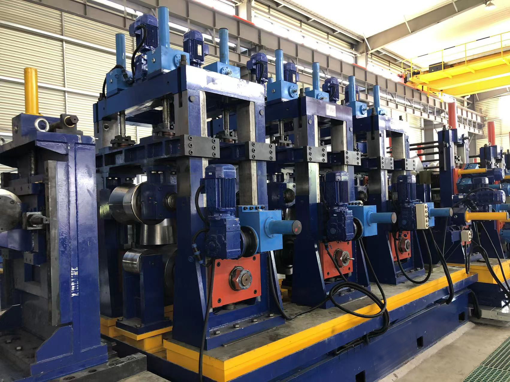
During the roll forming stage, a steel strip undergoes progressive plastic deformation to form a round profile before induction welding. If the strip enters the forming rolls with structural stress, variable tension, or lateral misalignment, the resulting tube will exhibit defects such as twist, side-bend, or mismatched weld seams. Controlling these variables begins at the coil entry stage.
Steel coils arrive at the processing facility tightly wound, retaining substantial residual bending stress, commonly referred to as coil set. As the coil unwinds, this stored energy is released unevenly. Without precise back-tension and physical containment, the material can experience clock-springing, where the outer wraps expand rapidly and uncontrollably. This creates severe operational hazards and damages the strip edges.
To prevent these issues, the payout system must perform three distinct operational functions:
Securely grip the inner diameter of the coil to prevent slippage during acceleration and deceleration phases.
Provide consistent, adjustable braking torque to maintain appropriate back-tension, preventing strip sag or over-travel.
Keep the strip centerline aligned with the entry guide of the shear and butt welder or strip accumulator.
From a structural standpoint, the machine frame must withstand massive cantilevered loads. The weight of a standard steel coil can range from 3 metric tons to over 20 metric tons, depending on the mill capacity. Because this mass is supported from a single side on an expanding mandrel, the spindle bearings and housing are subjected to severe bending moments.
Heavy-duty systems utilize a solid forged alloy steel spindle, heat-treated for fatigue resistance and machined to tight tolerances. This spindle is housed within a heavy, stress-relieved steel plate frame. Manufacturers like SANSO design these structural components to minimize deflection under maximum load, which is necessary for maintaining precise horizontal alignment with downstream leveling equipment.
Depending on the production volume and line configuration, plants deploy either single-mandrel or double-mandrel designs:
This layout features one expanding spindle mounted on a stationary or sliding base. It is highly effective for medium-capacity lines where coil changeover times do not limit overall productivity. The entire unit can be mounted on a sub-base equipped with hydraulic positioning cylinders, allowing for active side-shift adjustment to correct strip tracking in real time.
Commonly referred to as a rotary or dual-head uncoiler, this design incorporates two separate mandrels mounted on a central indexing platform. While one mandrel feeds the active production line, the second mandrel can be safely loaded and prepared with a new coil. Once the active coil is exhausted, the platform rotates 180 degrees, bringing the fresh coil into the feeding position within minutes. This configuration is widely used in high-frequency welding plants equipped with strip accumulators to run continuous, uninterrupted cycles.
Gripping the internal coil surface securely is essential to prevent internal slippage, which can score the material or cause erratic tension. The mandrel consists of segmented leaves that expand radially outward to engage the inner diameter of the coil.
Manual expansion designs rely on a mechanical wedge or screw link system. The operator rotates an adjustment screw, which drives slide blocks along inclined planes to push the segments outward. While cost-efficient and reliable for light coils under 3 tons, manual systems are physically demanding and lack the clamping force required for heavy industrial applications.
For high-performance environments, hydraulic expansion is the standard. In a hydraulic uncoiler, a rotary hydraulic cylinder mounted at the rear of the main shaft acts on a central drawbar. This drawbar pulls a wedge expansion mechanism located inside the mandrel, forcing the outer segments outward with consistent radial pressure. This hydraulic mechanism offers several processing advantages:
Consistent radial force prevents internal coil collapse or deformation of the inner steel wraps.
Adjustable pressure settings allow operators to match the gripping force with the yield strength and wall thickness of the coil.
Rapid expansion and contraction cycles significantly reduce coil changeover times, improving overall plant efficiency.
To accommodate variations in master coil dimensions, these mandrels are engineered to cover standard inner diameter ranges, typically 480 mm to 520 mm. For larger coil specifications, heavy-duty bolt-on adapter shoes or filler plates are secured to the segments, extending the working expansion range up to 610 mm or more.
As the strip travels through the forming mill, the payout reel must not spin freely; doing so would result in material looping, strip buckle, and eventual line jams. A controlled resistance, or back-tension, must be maintained. Generating this tension requires a coordinated braking system capable of adjusting its output as the coil diameter decreases.
During a production run, the outer diameter of the coil continuously shrinks, reducing the torque arm. If the braking torque remains constant, the actual tension pulled by the downstream feed rolls will rise proportionally. To counteract this physical behavior, industrial uncoiler stations incorporate dynamic tension control systems.
Pneumatic disc brakes are frequently used for light to medium-duty applications. These systems employ proportional pressure valves linked to a coil-diameter tracking sensor, such as an ultrasonic distance meter or a mechanical riding arm. As the sensor detects a reduction in coil diameter, the control system reduces the pneumatic pressure to the brake calipers, keeping the strip tension stable.
In high-speed, heavy-gauge lines, motorized systems with regenerative AC drives are often preferred. Here, the motor acts as a generator, supplying controlled back-tension while feeding electrical energy back into the plant grid. This approach provides precise control during the rapid acceleration and emergency stop phases of the tube mill.
Handling thick-walled or high-strength steel coils introduces mechanical challenges that require dedicated auxiliary devices. High-yield carbon steel displays a strong tendency to uncoil rapidly when the strapping bands are severed. To manage this safely, a heavy-duty hold-down arm, or snubber arm, is positioned above the mandrel.
The snubber arm is hydraulically lowered onto the outer diameter of the coil. Equipped with a motorized polyurethane-coated press roll, it applies constant downward force, allowing the operator to safely cut the banding straps. The motorized roll then assists in threading the leading edge of the strip into the leveling unit.
Another common issue is material misalignment, or camber, where the strip curves slightly along its length. If the coil is loaded off-center on the mandrel, this error propagates down the line. To resolve this, the uncoiling station is frequently paired with an automated coil loading car. The coil car lifts the coil hydraulically, matches its height to the mandrel centerline, and travels horizontally to slide the coil onto the expanded mandrel leaves, preventing physical damage to the machine components.
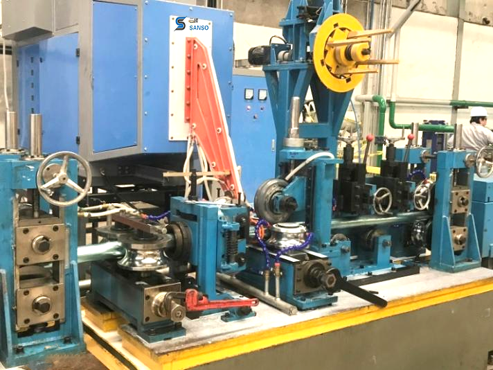
The efficiency of a high-frequency welded tube line manufactured by SANSO depends on seamless integration between the feeding section and the downstream welding mill. In a modern setup, the uncoiling unit does not operate in isolation. It is part of a synchronized system linked directly to the loop accumulator and the main PLC control panel.
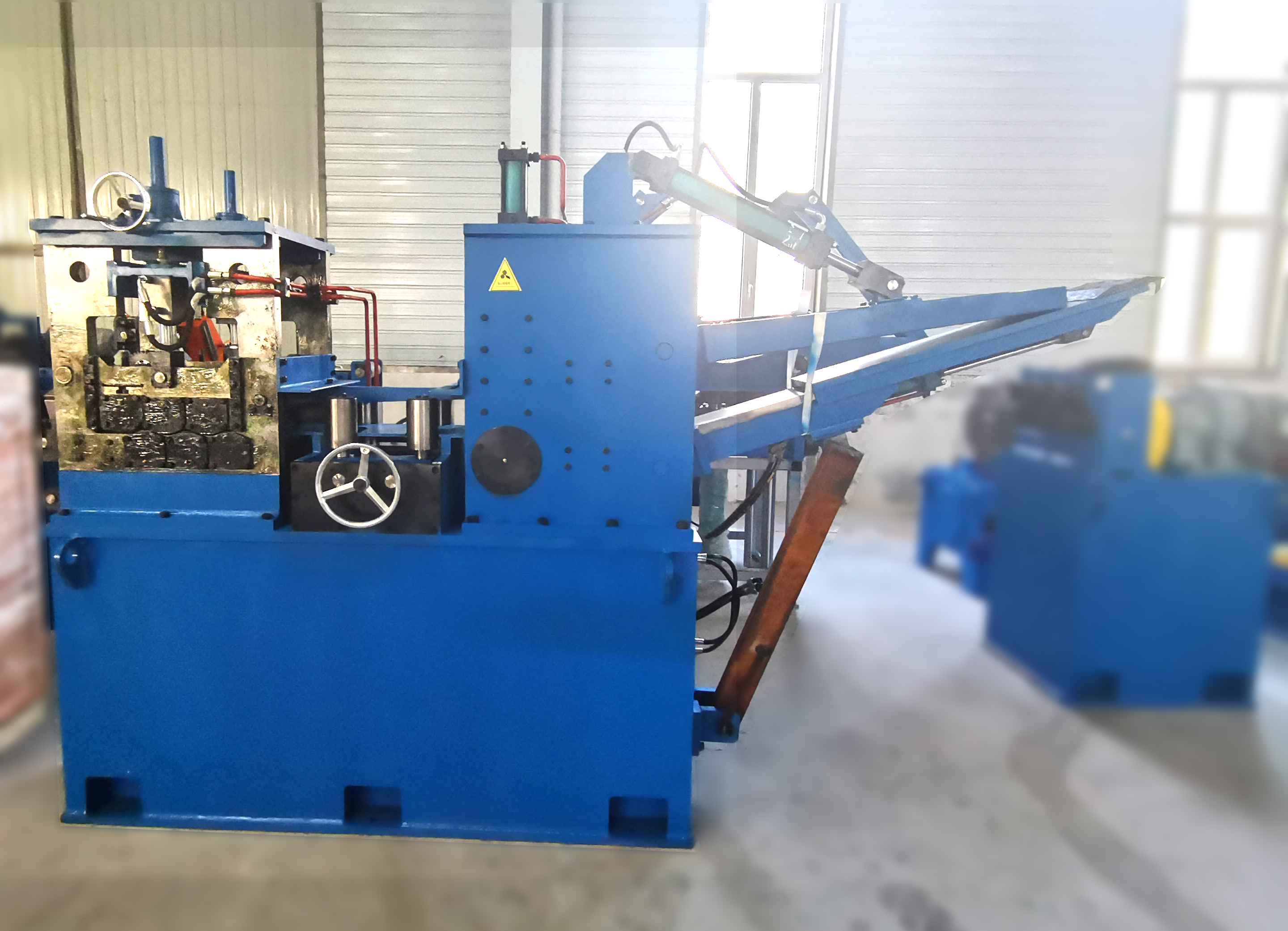
When starting a new coil, the leading edge is directed through a peeling table and a pre-leveling unit, which flattens the strip end so it can be welded to the trailing edge of the previous coil. The shear and butt welder crops both ends and welds them together, ensuring a continuous strip flow. During this temporary stoppage at the welding station, the downstream accumulator continues to feed the active forming mill, preventing any stop-start defects in the weld seam of the finished tube.
To ensure this continuous sequence works reliably, sensor arrays monitor loop depth in a loop pit or accumulator feed tower. These sensors send real-time analog signals to the payoff drive, automatically adjusting the rotation speed of the uncoiler to match downstream demand without jerking or stalling the steel strip.
When specifying a payoff reel for a tube manufacturing facility, engineering teams should evaluate several operational parameters to ensure long-term reliability:
| Parameter | Engineering Significance | Standard Industry Ranges |
|---|---|---|
| Maximum Coil Weight | Determines spindle bearing sizing and shaft deflection limits. | 3,000 kg to 25,000 kg |
| Strip Width Range | Defines the axial length of the mandrel leaves and structural footprint. | 50 mm to 1,600 mm |
| Material Thickness | Dictates the required braking torque and need for a hold-down arm. | 0.5 mm to 16.0 mm |
| Mandrel Expansion Range | Must match the internal diameter of incoming mill coils. | Ø470 mm – Ø520 mm (expandable to Ø610 mm) |
| Line Speed Matching | Ensures synchronization with high-speed forming mills without loop lag. | Up to 120 meters/minute |
By aligning these parameters with the chemical and physical properties of the target steel grades, tube manufacturers can avoid issues like coil slippage, strip deformation, and premature mechanical wear on the spindle bearings.
A1: While both terms are frequently used interchangeably in the metal processing industry, a decoiler often refers to a simpler, sometimes passive, non-motorized reel that relies entirely on the pull of downstream machinery. In contrast, an industrial payoff reel or uncoiling unit typically features active components, such as integrated hydraulic expansion systems, dynamic pneumatic or regenerative braking systems, and motorized snubber arms to handle heavier coil weights and high-speed tube mill integration safely.
A2: A loop control system monitors the slack portion of the strip situated between the payout station and the first feed roll or accumulator. Utilizing ultrasonic distance sensors, photoelectric arrays, or a mechanical dancer arm, the system measures the depth of the material loop. This sensor output is processed by a PLC to adjust the braking pressure or the variable speed drive motor on the mandrel spindle, speeding up or slowing down rotation to match the line speed.
A3: To manage high-strength materials safely, machines are equipped with a hydraulic snubber arm (hold-down arm) that presses a heavy, motorized roller directly onto the outer diameter of the coil. This physical restraint keeps the coil wraps tightly bound while the steel banding straps are cut. Additionally, heavy-duty side guide rollers and peeler shovels are used to guide the springy outer wrap into the pinch rolls without manual handling.
A4: Mandrels are engineered with a base expansion range, typically operating between 470 mm and 520 mm via hydraulic wedge actuation. When a plant processes coils with larger inner diameters, such as 610 mm, operators install bolt-on segments or sector plates over the standard mandrel leaves. This extends the outer clamping diameter while retaining full structural rigidity and hydraulic grip force.
A5: Back-tension is necessary because it prevents the steel strip from slackening, which can cause lateral wandering, edge damage, and telescoping (where the center of the coil slides outward horizontally). Maintaining a constant, controlled tension ensures that the material enters the leveling machine and forming rolls perfectly flat and aligned with the machine centerline, which directly improves the geometry of the welded tube.
Selecting the correct material handling machinery requires a detailed analysis of your production line, material specifications, and yield strengths. The engineering team at SANSO specializes in designing custom tube mill entry systems, including heavy-duty single and double-head coil payoff stations, tailored to your specific operational goals. To discuss your production parameters or to receive a detailed technical proposal for a high-performance entry system, please submit a formal inquiry with your coil dimensions and line speed requirements.