Before any strip steel enters the forming section of an ERW tube mill, the quality of the incoming coil and the performance of upstream machinery determine weld consistency, dimensional accuracy, and overall yield. This sequence of machinery—collectively known as coil processing equipment—must handle uncoiling, leveling, end joining, buffering, and edge trimming with minimal intervention. Based on field data from 22 pipe plants in Southeast Asia and the Middle East, we examine six critical checkpoints that separate reliable lines from those plagued by coil breaks and weld rejects.
The uncoiler is the first station in any coil processing equipment lineup. Its primary tasks: support the coil, control pay-off speed, and maintain constant back tension to prevent strip telescoping. Two common configurations exist—single mandrel with hydraulic expansion (for heavy coils up to 25 tons) and double-cone uncoilers (for lighter, narrow strips). Field experience shows that inconsistent braking torque causes edge wave formation and surface scratches. A modern uncoiler integrates a closed-loop tension control with dancer roll feedback, maintaining strip tension within ±5% of the setpoint. For API 5L X70 coils (thickness 6–12 mm), recommended back tension ranges from 12 to 18 N/mm² of cross-section. When tension drops below 8 N/mm², the strip may wobble inside the pinch rolls, introducing camber.
After uncoiling, the leading edge passes through a pinch roll set (motorized lower roll, pneumatically loaded top roll) and then a multi-roller leveler. The leveler removes coil set, edge wave, and center buckle. Key parameters:
Number of work rolls: 7–9 rolls for thin gauge (≤4 mm), 11–13 rolls for heavy plate (≥8 mm).
Roll diameter and pitch: smaller pitch (60–80 mm) improves flatness but requires higher precision bearings.
Adjustable backup rolls: individual screw-downs allow zone-specific flattening.
In many lines, coil processing equipment suffers from leveler overload when edge drop exceeds 0.3 mm. One solution: install a hydraulic anti-cluster leveler with integrated load cells that automatically adjusts roll penetration per meter of strip length. Data from a 16-inch line (WT 9.5 mm) showed a 58% reduction in wave defects after retrofitting such a system. The leveler must also handle the welded joint from the previous coil—a transition that requires temporarily lifting the work rolls.
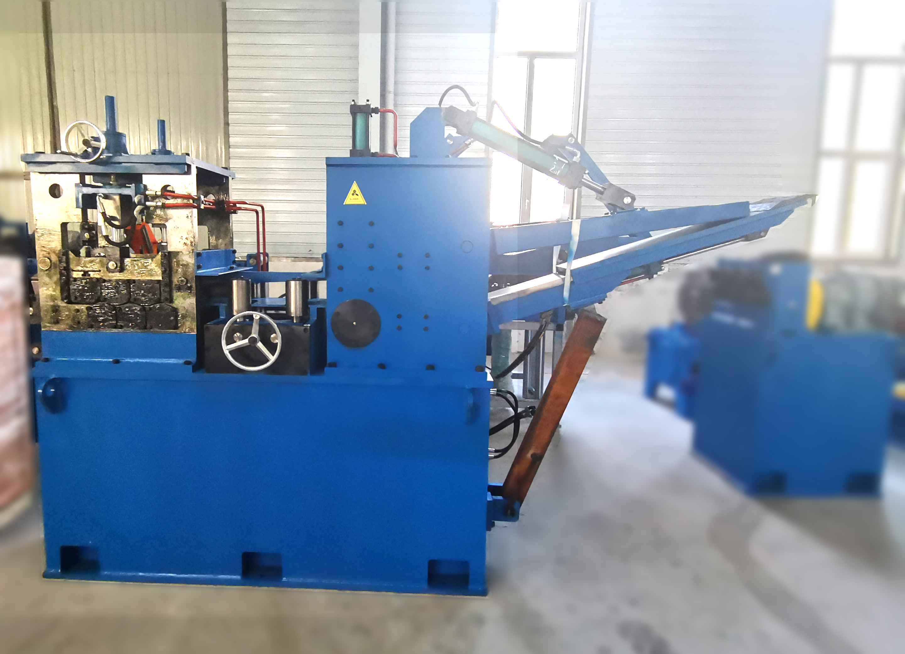
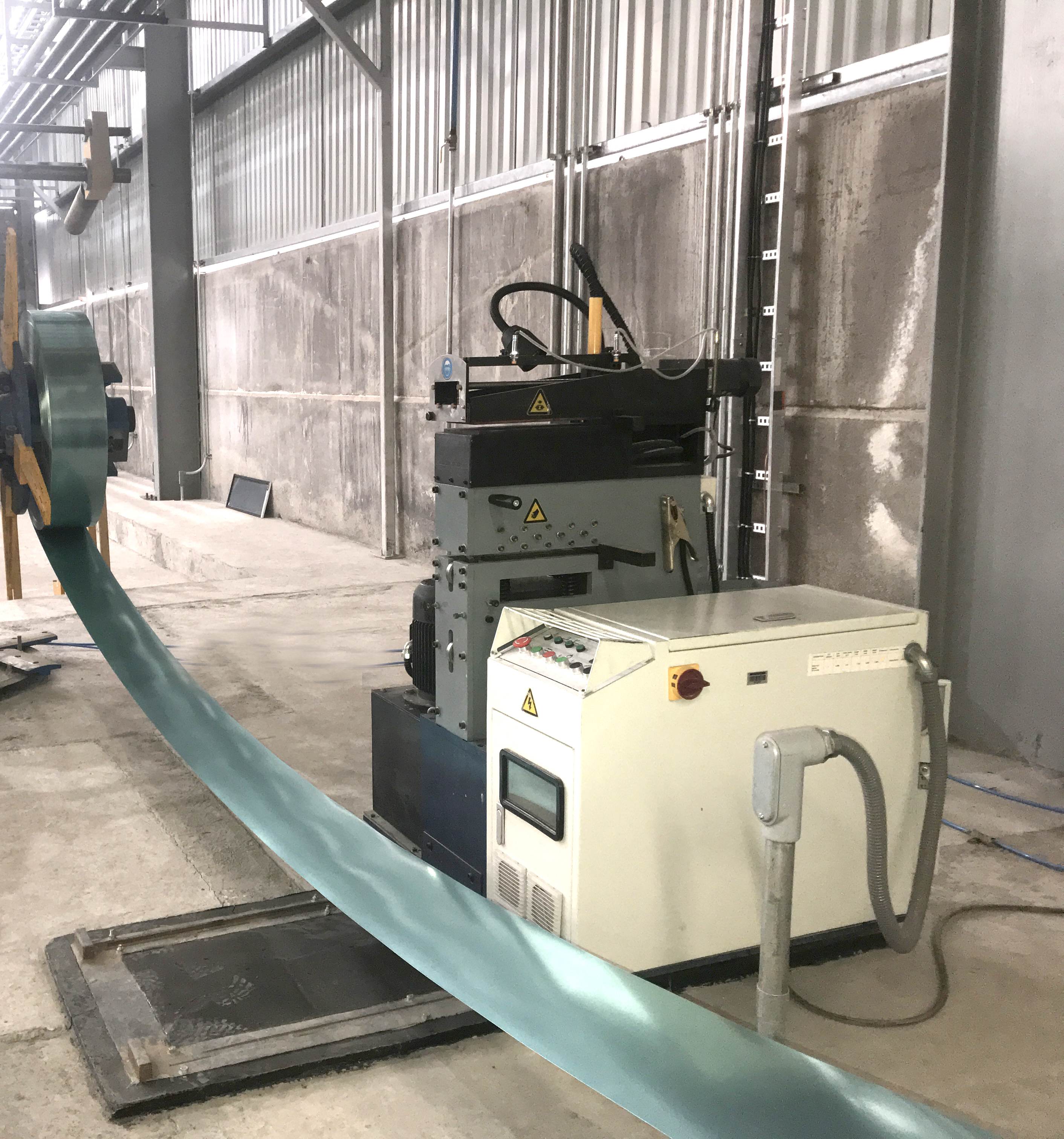
To enable continuous operation, the tail end of an exhausted coil is sheared and welded to the head of the next coil. The shear must produce a perfectly square cut (≤0.5 mm deviation per 100 mm width) to avoid misalignment during welding. Two welding methods dominate:
Lap welding: Faster (15–20 seconds) but leaves a double-thickness overlap that may damage forming rolls.
Butt welding with upsetting: Produces a smooth joint (flash height ≤1 mm) but requires precise clamping.
For high-strength steel (750 MPa tensile), a solid-state HF welder with automatic edge alignment is recommended. When the weld joint passes through the coil processing equipment, the downstream accumulator must absorb line speed variations. A common failure point is the weld bead’s hardness—excessive quenching leads to cracks. Installing a localized induction tempering station after the welder reduces hardness to <280 HV, matching the base metal.
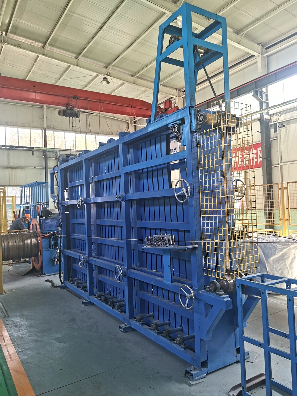
The accumulator (horizontal or vertical) stores enough strip length to keep the tube mill running while the coil processing equipment stops for a new coil. Two types are used:
Horizontal looping pit (caterpillar type): Up to 200 m storage, ideal for heavy-wall pipes but requires large floor space.
Vertical tower accumulator: Compact, with 100–150 m capacity; uses servo-driven carriages to maintain constant strip tension.
Accumulator performance directly affects line uptime. If the exit tension from the accumulator varies by more than ±3%, the forming section experiences strip steering errors. Advanced systems employ load cell feedback to regulate the pinch roll speed. A case study from a 10″ hydraulic tube mill reported that upgrading to a vertical accumulator with active dancer rollers reduced weld seam wandering by 42%. The accumulator also acts as a buffer during emergency stops—its maximum acceleration should reach 1.5 m/s² to prevent loop collapse.
Although many mills receive pre-slit coils, integrated coil processing equipment sometimes includes a rotary trimming shear to correct edge burrs or remove ragged edges. Two aspects matter:
Clearance between rotary knives: 5–8% of strip thickness for mild steel, 10–12% for high-strength low-alloy (HSLA).
Overlap of knives: 0.2–0.5 mm; incorrect overlap causes burr height >0.2 mm, leading to poor HF welding.
For mills producing API 5L PSL2 line pipe, edge milling is often preferred over trimming because it generates a precise bevel (35–40°). A modern edge milling unit integrated with the coil processing equipment includes laser edge detection to maintain a 0.1 mm root face. Removing edge defects before forming can lower the rejection rate from weld porosity by up to 60%. For economical grades (ASTM A53), trimming alone is sufficient if the incoming slit edge has burrs below 0.1 mm.
The final stage of coil processing equipment is the transition guide table that feeds perfectly flat, burr-free strip into the breakdown rolls. This interface is often overlooked yet critical. Parameters to monitor:
Strip centerline deviation: must stay within ±1.5 mm over 10 m; otherwise, the fin passes introduce uneven edge heating.
Mismatch between exit speed of processing line and entry speed of tube mill: speed difference >2% triggers micro-slips, scratching the strip surface.
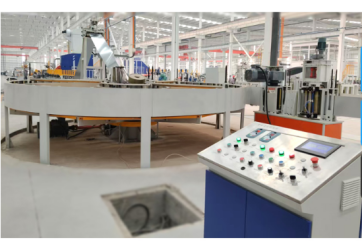
Many modern lines employ a master-slave drive architecture where the tube mill’s main motor sets the speed reference, and all upstream processing equipment follows. SANSO provides integrated control cabinets with real-time torque sharing between the leveler, pinch rolls, and forming stands. This coordination is particularly vital when producing thin-wall (<2 mm) mechanical tubing, where any tension spike can cause strip tearing.
From audits of 14 tube mills, the five most frequent issues related to coil processing equipment and their resolutions are:
Coil break marks on the strip surface → Reduce uncoiler braking force and install a rubber-lined pay-off drum.
Inconsistent leveling causing wavy edges → Replace worn backup rolls; perform roll parallelism check every 2,000 operating hours.
Weld joint breaks under tension → Switch to butt welding with 1.2 mm upset; add post-weld annealing using an induction coil.
Accumulator loop sagging during acceleration → Increase air pressure in the dancer cylinders or upgrade to servo-motor controlled carriages.
Edge burrs after trimming >0.15 mm → Adjust rotary shear clearance to 6% of thickness; use carbide knives for HSLA grades.
For pipe makers looking to reduce downtime, retrofitting the coil processing equipment with predictive maintenance sensors (vibration on uncoiler bearings, thermography on leveler motors) typically pays back within 8 months.
Oil & gas pipe mills (API 5L X65–X80): Require edge
milling, ultrasonic testing of the strip edges, and an accumulator capable of
storing 200 m due to frequent weld inspections.
Structural tube (EN
10219 / ASTM A500): High speed (50–70 m/min) demands a fast
shear-welder system (cycle time ≤25 seconds) and a vertical accumulator with low
inertia rolls.
Boiler tube (ASTM A179): Extremely sensitive
to surface scratches; must use rubber-lined pinch rolls and no trimming—instead,
request pre-slit coils with <0.05 mm burr.
Stainless steel tube
(AISI 304/316): Requires separate uncoiler liner plates to avoid carbon
contamination; the leveler rolls must be hardened to HRC 58–62 to prevent roll
marking.
SANSO has supplied complete coil processing equipment for more than 190 tube mills worldwide. Each system undergoes finite element analysis (FEA) for uncoiler mandrel deflection and leveler roll bending. Their latest generation integrates a digital twin for strip tracking, predicting edge wander before it occurs. For a recent 8″ line in Malaysia, SANSO achieved a first-pass yield of 97.4% during the second week of commissioning—partly due to an adaptive accumulator tension algorithm that reduces strip stress variation by 62% compared to conventional PID control. The modular design allows future addition of an edge milling station without modifying the base frame. SANSO also provides remote diagnostic services, using historical data to predict when uncoiler brake pads need replacement.
Q1: How do I calculate the required storage length of an accumulator
for my coil processing equipment?
A1: Determine the time needed to
prepare a new coil (shear, weld, and restart) — typically 45–90 seconds.
Multiply that by the line speed (m/s). For a mill running at 40 m/min (0.67 m/s)
with 70 seconds preparation, you need 46.9 m of strip storage. Add 20% safety
margin → minimum 56 m. For high-speed lines (>60 m/min), a vertical
accumulator with 120–150 m capacity is recommended.
Q2: What is the acceptable leveler roll wear before it affects strip
flatness?
A2: Work roll diameter reduction of >0.5 mm or surface
hardness drop below HRC 55 will degrade flatness, particularly on edges. Measure
roll diameter every 1,500 operating hours. If the worn roll creates a 0.1 mm
deep groove, the strip will exhibit center buckle. Re-grinding is possible down
to 4 mm below original diameter.
Q3: Can I run both hot-rolled and cold-rolled coils through the same
coil processing line?
A3: Yes, but two adjustments are necessary:
(a) The pinch roll pressure for hot-rolled (scale present) should be 30–40%
higher due to lower friction coefficient. (b) The leveler’s roll penetration
must be increased by 0.2–0.4 mm for hot-rolled to break scale and reduce coil
set. Also, consider adding a scale breaker (a set of small-diameter rolls)
before the leveler to avoid scale embedment.
Q4: How does the edge trimming shear affect the downstream welding
quality?
A4: If the trimming leaves a burr taller than 0.18 mm, the
high-frequency current tends to jump across the burr, causing uneven heating and
a cold lap defect. Use a de-burring station (rotary wire brush) immediately
after trimming to reduce burr height to ≤0.1 mm. For pipes used in sour service
(NACE MR0175), edge milling is mandatory instead of trimming.
Q5: What is the typical electrical power consumption of a complete
coil processing system for a 10″ tube mill?
A5: For a line
processing 12 mm thick × 300 mm wide strip at 20 m/min: uncoiler brake (1.5 kW),
leveler drives (22 kW), pinch roll motors (2×5.5 kW), accumulator hydraulic
power unit (7.5 kW), and shear/welder (peak 15 kW) → average consumption 35–40
kWh per operating hour. Adding an edge mill adds ~11 kW. Energy-efficient lines
use regenerative drives on the leveler, recovering up to 30% of braking
energy.
Q6: How often should the uncoiler mandrel expansion segments be
lubricated to avoid coil slippage?
A6: Grease the sliding surfaces
every 1,000 coil changes or every 500 operating hours, whichever comes first.
Use high-pressure lithium grease (NLGI grade 2). Signs of inadequate
lubrication: the coil slips during deceleration, causing scratches on the inner
wraps. For heavy coils (>15 tons), inspect the expansion wedges for wear
every 3,000 hours.
Selecting or upgrading your coil processing equipment is a decision that directly impacts your tube mill’s efficiency, scrap rate, and ability to meet strict standards (API, ASTM, EN). Whether you need to reduce changeover time between different coil widths or eliminate edge burrs for high-frequency welding, the technical parameters described above provide a roadmap.
For a process audit or a customized quotation based on your monthly tonnage, material grades, and available floor space, contact SANSO’s engineering team directly. Provide your coil specifications (width range, thickness range, coil ID/OD) and desired line speed—and receive a detailed proposal within 7 working days.
Send your coil processing line requirements for a rapid ROI analysis — include strip width, wall thickness range, and target output (tons/week).