The reliability of a longitudinally welded steel pipe begins with the precision of its ERW mill. From skelp edge milling to final ultrasonic testing, each station determines the mechanical strength, dimensional consistency, and corrosion resistance of the finished product. This article examines seven critical parameters that separate high-yield production lines from those plagued by seam rejects and frequent downtime. Drawing on field data from API 5L and ASTM A53 operations, we also present engineering solutions validated across multiple plants.
Before forming, the steel strip (skelp) must undergo precise edge milling. The edge geometry directly influences the high-frequency welding process. A 35–40° bevel angle with a root face of 0.1–0.3 mm provides optimal current penetration and minimizes flashing. Many operators ignore the effect of burr height — any edge burr exceeding 0.15 mm can lead to scattered arc spots and cold welds. Modern lines integrate inline edge milling units with ±0.05 mm accuracy and laser-based profile monitoring. This reduces the scrap rate associated with poor edge fusion by up to 40%.
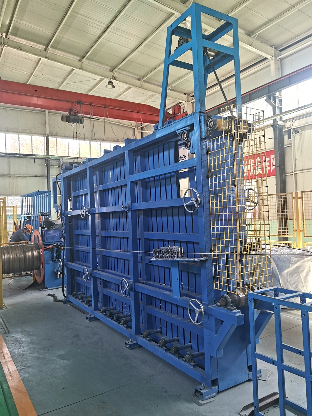
The transition from flat strip to open tube is governed by three forming zones:
Breakdown section (6–8 stands): Progressive bending with bottom-driven rolls; the strip edge lift must not exceed 2° per pass to avoid edge waves.
Fin passes (2–3 stands): Closing the gap; typical fin angle closure of 12–15° per stand for wall thickness 4–10 mm.
Side rolls (cage rolls): Control the open gap width (1.5–2.5× wall thickness) before entering the welding unit.
When forming high-strength grades like API 5L X65, roll spring-back compensation becomes necessary. A well-optimized forming sequence reduces residual stress and ensures the weld groove alignment is within 0.2 mm. Several pipe mills have retrofitted their ERW mill with staggered breakdown roll sets to accommodate a wider range of diameters without changing the entire tooling.
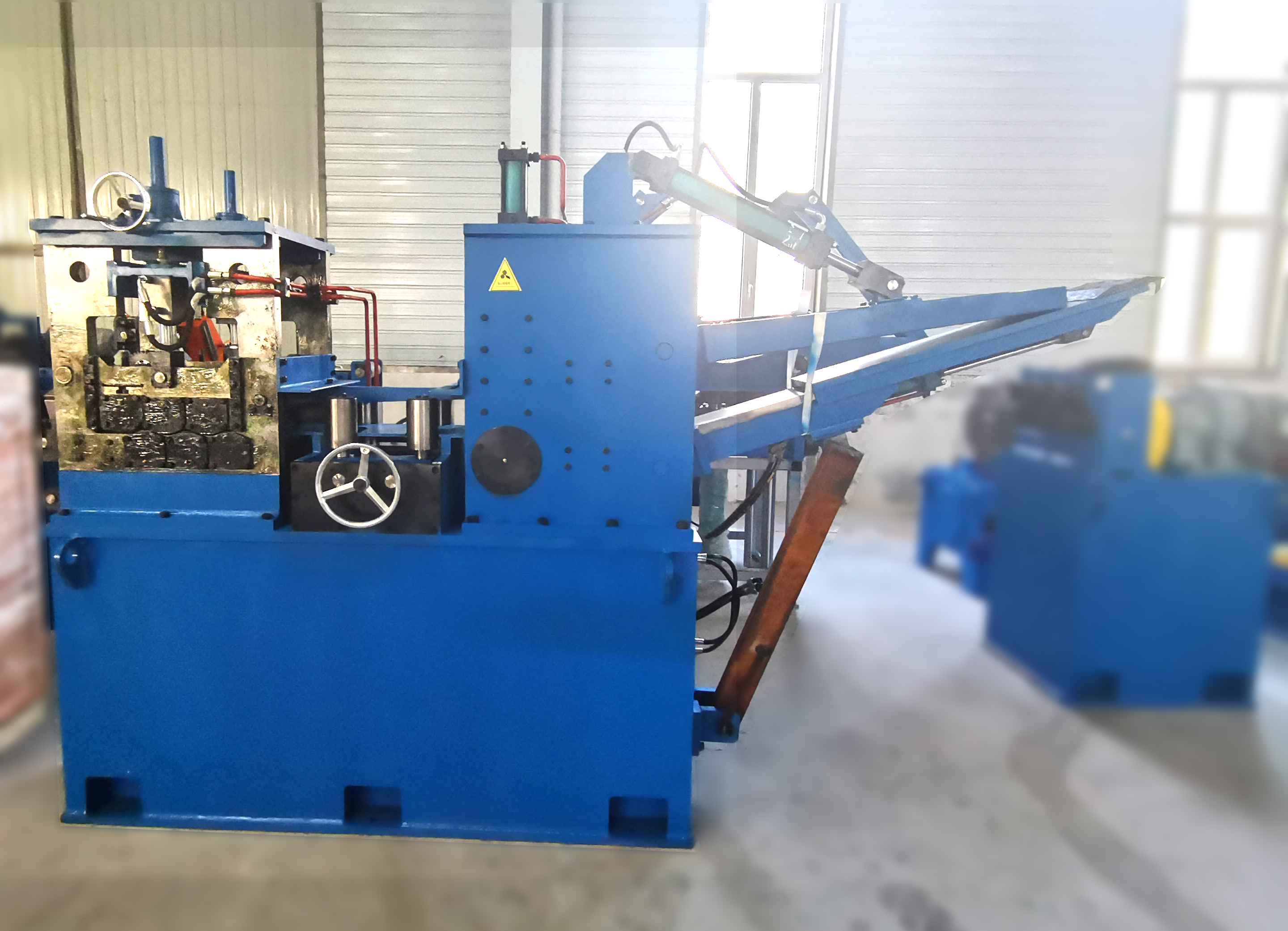
The welding station remains the most scrutinized part of the line. Two main HF technologies exist: contact welding (lower frequency, 200–300 kHz) and induction welding (350–450 kHz). For wall thickness above 8 mm, induction welding provides a more stable heat pattern. Key variables include:
Welding speed vs. frequency: Speed above 25 m/min requires frequency adjustment to keep V-angle (the convergence angle of edges) between 3° and 7°.
Impeder positioning: The ferroxcube impeder must remain centered within 1 mm of the weld point; deviation causes preferential heating on one edge.
Squeeze roll pressure: Upset target of 1.8–2.2 mm for heavy wall pipes; insufficient squeeze produces incomplete fusion, while excessive squeeze generates excessive flash (IRO) and reduces productivity.
Data from a 12-inch line (WT 9.5 mm) showed that adjusting the impeder gap from 5 mm to 3.8 mm reduced the internal flash height by 32%. SANSO supplies automatic welding power controllers that maintain optimal heat input (±2% variation) despite line speed fluctuations caused by strip weld joints.
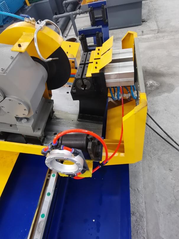
After welding, the inner bead (internal flash) must be trimmed to ensure smooth flow in fluid conveyance and to avoid stress risers. IRO systems use a carbide-tipped blade mounted on a mandrel. Parameters that affect clean removal:
Blade rake angle: negative 5–10° for wall thickness >6 mm.
Blade protrusion above tube ID: 0.1–0.2 mm for API 5L B, up to 0.4 mm for softer grades.
Back-up roll pressure: 600–800 N to prevent tube distortion.
External flash knives produce a smooth outer surface. However, if the trimming operation leaves height above 0.3 mm, it may interfere with coating adhesion. Recent developments include servo-controlled IRO with laser displacement sensors that adjust blade height in real time. One manufacturer reported a 65% reduction in inner bead-related rejects after upgrading their ERW mill with closed-loop flash control.
Microstructural transformation in the heat-affected zone (HAZ) is inevitable. To restore toughness, especially for sour service applications (NACE MR0175), an inline post-weld heat treatment (PWHT) station is mandatory. Two methods dominate:
In-line induction annealing: Heating the weld seam to 900–950°C followed by air cooling; refines the coarse grain structure.
Full-body normalizing: For larger diameters, but requires a separate furnace and slows the line.
The effectiveness is verified by transverse guided bend tests and Charpy V-notch impact values. Acceptable targets at -20°C: >40J for line pipe. Without proper PWHT, the weld zone can fail at stress levels 30% lower than the base metal. Modern ERW mill configurations integrate infrared temperature monitoring and PLC-controlled heating power to maintain soak time within ±0.5 seconds.
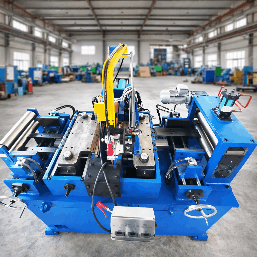
After welding and heat treatment, the tube passes through a sizing section (4–6 stands) to achieve final OD tolerance (typically ±0.5% for A53). Key considerations:
Roll gap reduction per stand: 0.3–0.6% of OD; excessive reduction leads to work hardening and ovality.
Straightening overhang: A 7-roll straightener with offset rolls reduces residual helix curvature to below 1 mm per meter.
On-line ultrasonic thickness monitoring (UT) combined with an automatic feedback loop to adjust stand screw-downs.
Plants producing structural pipes (EN 10219) often ignore the effect of cooling water distribution after sizing, leading to lobar deformation. Using rotary cooling sections with adjustable nozzles can reduce ovality from 1.5% to 0.6% on 300x300 mm square tubes. SANSO offers integrated sizing stands with quick-change cassettes, reducing changeover time to under 45 minutes.
No ERW mill can operate without a robust inspection protocol. The minimum requirements per API 5L include:
Eddy current testing (ECT) for surface and near-surface defects on the weld area.
Ultrasonic testing (UT) for laminations and lack of fusion, using phased array probes covering 100% of the weld.
Hydrostatic test (proof pressure = 90% of specified minimum yield strength) with dwell time of at least 10 seconds.
Data management becomes critical when traceability is required for 20-year lifecycle tracking. Advanced lines automatically record each pipe’s weld heat input, flash trim force, and NDT results, linking them to a barcode. MES-integrated inspection reports reduce human error and allow root cause analysis when a batch of pipes fails. One case study showed that by adding real-time UT‑based weld centering correction, a 16″ line improved first-pass yield from 92.4% to 98.1%.
Based on audits of 14 tube mills in Southeast Asia and the Middle East, the most common challenges—and their fixes—are:
Weld porosity → Check strip edge cleanliness; install high-pressure air knives before the forming section.
Fluctuating weld flash height → Verify impeder cooling water flow and replace worn squeeze rolls.
Helical pipe (twist) → Realign fin pass roll axis horizontally; adjust straightening roll tilts.
High frequency generator trips → Upgrade cooling system and inspect coaxial cable insulation.
Tooling wear causing wall thickness variation → Implement scheduled roll dressing based on tonnage, not time interval.
For operators seeking to modernize their existing lines, retrofitting with ERW mill automated weld management systems typically provides payback in less than 10 months due to reduced waste and lower energy consumption.

Oil & gas pipeline (API 5L PSL2): Requires full-body UT,
Charpy tests at -29°C, and low hardness in the weld (≤250 HV10). The mill must
incorporate online hardness monitoring via electromagnetic
sensors.
Structural & mechanical tubing (ASTM A500 / EN
10219): Cost efficiency is paramount. A high-speed line (50–70 m/min)
with quick-change roll sets and minimal heat treatment is
preferred.
Boiler tubes (ASTM A179): Extreme demands on
surface finish and absence of internal flash. A burr-free IRO combined with 100%
eddy current testing + eddy current for subsurface defects is
mandatory.
Water well casing (AWWA C200): Large diameters
(24–48″) with moderate wall thickness; the forming section requires robust side
roll supports to prevent strip buckling.
With over 240 installations worldwide, SANSO provides not just machinery but a process guarantee. Each ERW mill is simulated by finite element analysis (FEA) for roll forming forces and weld temperature distribution before manufacturing. Their service package includes remote digital twin monitoring and annual ultrasonic calibration. For a recent 8″ line in Texas, SANSO achieved a Cpk of 1.33 for OD tolerance within the first 48 hours of commissioning—without rework of the skelp edge preparation unit. The modular weld monitoring suite offers real-time defect flagging, enabling operators to reject individual pipes rather than whole bundles.
Q1: How do I determine the appropriate welding frequency for my ERW
mill when processing thin-wall (≤3 mm) vs. thick-wall (≥12 mm)
coils?
A1: For thin-wall (≤3 mm), use higher frequencies (400–450
kHz) to concentrate heat on the edge surfaces and avoid burning through; a
contact-type weld head is often more stable. For thick-wall (≥12 mm), a lower
frequency (200–280 kHz) with induction coil allows deeper current penetration.
The key is matching the frequency to the electrical resistivity of the steel
grade—for API 5L X70, stay above 300 kHz to prevent heat sinking into the base
metal.
Q2: What is the practical scrap rate improvement from adding an edge
milling machine with automatic burr detection?
A2: In a controlled
trial on a 10″ ERW line (WT 8 mm), conventional sheared edges caused 6.2%
rejects due to lack of fusion. After installing an automated edge mill with burr
detection (linked to online weld geometry
measurement), the scrap rate fell to 2.1% over six months.
Additional savings came from 40% longer squeeze roll life.
Q3: Can I run both round and square tubes on the same ERW mill
without major retooling?
A3: Yes, with certain compromises. A
universal forming section (breakdown + fin passes) designed for round pipes can
produce square/rectangular tubes by adding a turk’s head sizing block after the
welding station. However, the roll tooling for the fin passes must be changed.
Some modern mills use cluster-type fin rolls that
adjust horizontally, reducing shape changeover to 90 minutes.
Q4: How does inline tempering affect the production speed of an ERW
mill?
A4: Inline induction tempering (heating to 550–650°C for 2–5
seconds) typically reduces maximum line speed by 8–12% because the steel
requires enough dwell time to reach the target temperature uniformly. However,
it eliminates separate batch annealing, so overall throughput usually increases
by 15% when producing quenched-and-tempered grades (e.g., API 5L X80Q). The
speed reduction is offset by lower rejection rates.
Q5: What maintenance schedule prevents unexpected power loss from the
solid-state HF welder?
A5: For a 600 kW welder: every 800 operating
hours, inspect water-cooled capacitors and clean dust filters; every 1,500
hours, measure gate driver voltages and replace thermal paste on IGBT modules;
every 3,000 hours, perform a full impedance sweep and recalibrate the phase
control. Use thermography monthly to detect loose busbar connections. Following
this schedule reduces unplanned downtime by over 70%.
Q6: Is it necessary to install a laser ultrasonic system for weld
seam inspection, or is conventional UT sufficient?
A6: Conventional
piezo UT is sufficient for API 5L PSL1 and most structural pipes. However, for
high-frequency thin-wall (<4 mm) lines, piezo probes may suffer from
near-field resolution issues. Laser UT is justified for small-diameter (<60
mm) precision tubes or when the line speed exceeds 70 m/min, as it offers
non-contact scanning. For most operators, phased array UT with water coupling
provides the best cost-performance trade-off.
Selecting or upgrading an ERW mill is a strategic decision that affects pipe quality, energy consumption, and market responsiveness. Whether you need to expand your product portfolio to include high-strength line pipe or reduce changeover times for thin-wall mechanical tubing, the engineering details outlined above separate high-performing plants from the rest.
For a detailed process audit or a proposal tailored to your specific diameter range and production volume, contact SANSO’s technical sales team directly. Share your target standards (API, ASTM, EN) and current scrap rates, and receive a customized improvement roadmap within five working days.
Send your project requirements for a rapid quotation — include material grade, OD range, and target weekly tonnage.