The erw pipe mill remains the backbone of longitudinal welded pipe production, serving oil & gas transmission, structural piling, water lines, and automotive components. Unlike seamless rolling, electric resistance welding (ERW) combines cold forming with high-frequency edge heating, delivering consistent wall thickness, lower energy consumption, and shorter lead times. SANSO has engineered over 190 lines for diameters from 21.3 mm to 610 mm, processing grades up to API 5L X70. This article examines mill architecture, process physics, root-cause defect analysis, and field-proven solutions from a manufacturing engineering perspective.
A modern erw pipe mill integrates mechanical forming stations, a solid-state welder, post-weld heat treatment, and sizing sections. Each module's parameter window directly affects weld toughness and dimensional precision.
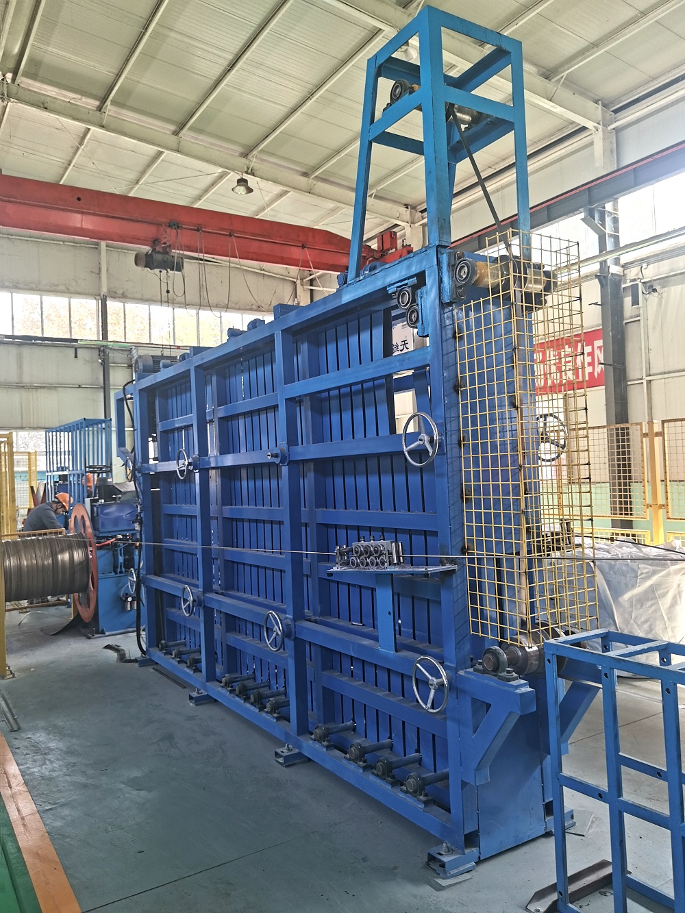
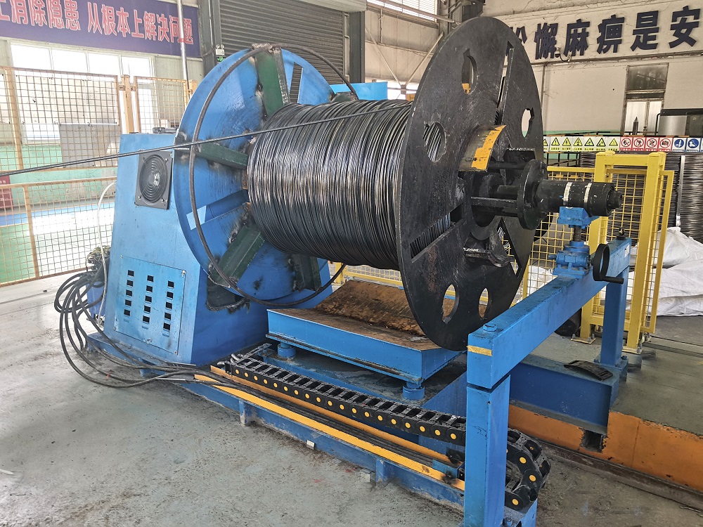
Hydraulic double-cone uncoiler – handles coils up to 25 tons, ID 508–760 mm, with automatic strip centering.
Horizontal loop accumulator – ensures continuous mill operation during coil change, maintaining line speed deviation below ±1.5%.
Edge milling unit – produces strip width tolerance ±0.3 mm; removes work-hardened edges to prevent cold weld defects.
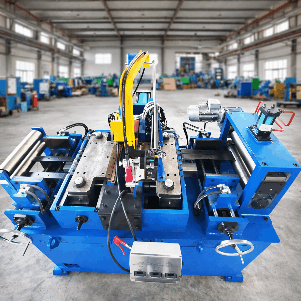
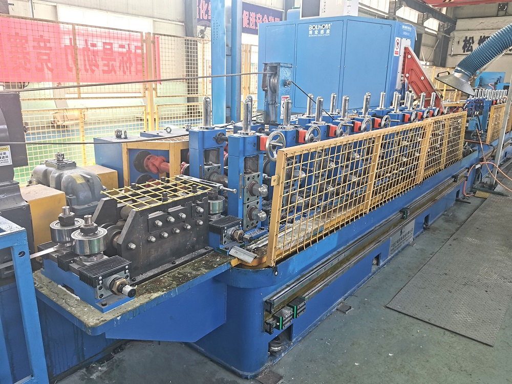
The forming zone converts flat strip into an open seam tube. Typical configuration: 5–7 breakdown stands, 3 side roll stands, and 2 fin pass stands. For heavy-wall pipes (>8 mm), cage forming technology reduces residual bending stress. Key forming parameters: inter-stand elongation <1.5%, edge gap variation ≤0.5 mm before welding.
Using a solid-state welder (350–600 kHz), the erw pipe mill induces eddy currents concentrated at the strip edges. A ferrite impeder placed inside the tube (2–3 mm from the weld point) improves power transfer efficiency. Optimal Vee angle: 4°–7°. Squeeze roll pressure (200–500 bar) expels molten metal, forming a forged seam with upset amount 0.8–1.2× wall thickness.
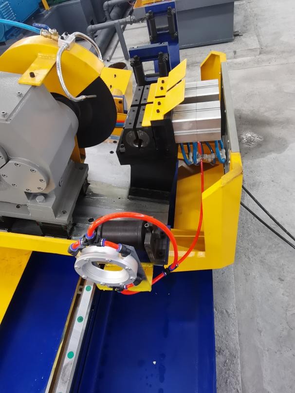
Internal/external carbide scarfing blades – remove flash bead; blade geometry with 12° rake angle achieves flush finish ±0.2 mm.
Water spray cooling (15–35 m³/h) – controls HAZ cooling rate to avoid martensite formation in carbon steels.
2-roll or 4-roll sizing mill – final OD tolerance to ASTM A500: ≤ ±0.5% with straightness ≤ 1.5 mm per meter.
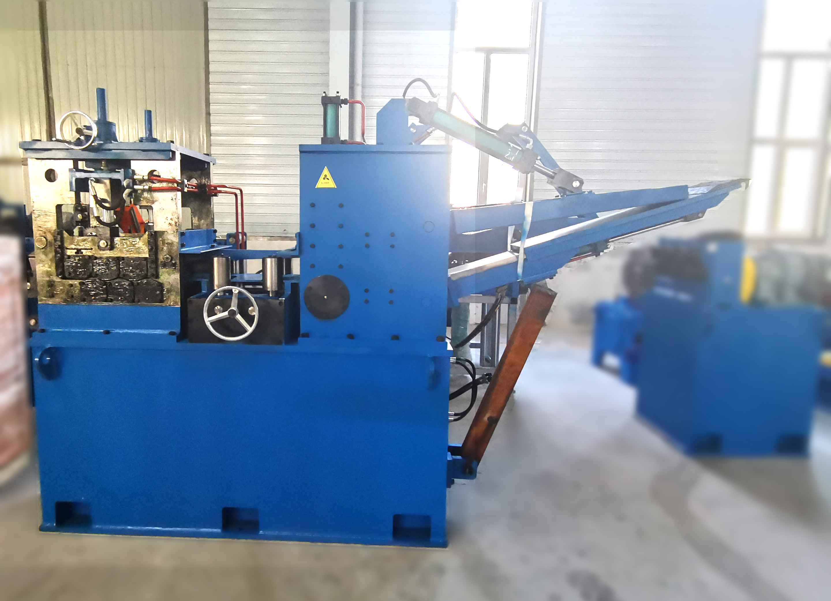
Servo-driven flying saw with cutting length accuracy ±3 mm (range 6–18 m). Downstream end-facing units bevel pipe ends to API 5L specification (30°±5°). SANSO mills include rapid tool change cassettes, reducing diameter changeover to under 40 minutes.
Mill operators must monitor these eight variables to maintain weld strength (≥95% base metal tensile) and ovality below 0.8%:
Strip width/thickness ratio – recommended 25–60; lower ratio requires additional breakdown passes.
Welding power & frequency interaction – higher frequency reduces heat-affected zone width but demands precise impeder alignment.
Squeeze roll gap & overlap – overlap (inside displacement) of 0.5–0.8 mm ensures forged grain flow across seam.
Cooling gradient – from 1450°C to 600°C in ≤2 seconds prevents coarse grain boundary precipitation.
Forming roll runout – maintain ≤0.06 mm to avoid periodic wall thinning.
Fin pass downforce – load cells should indicate <15 kN per side; excessive force causes edge buckling.
Line speed synchronization – all driven stands must stay within ±0.8% speed deviation.
In-line NDT calibration – eddy current or ultrasonic setups must be verified every shift using reference defects.
Despite advanced controls, weld-related defects account for 70% of pipe rejections. Below are five frequent failure patterns with specific remedies implemented at SANSO customer sites.
Root causes: insufficient heat input (below 180 kW/mm²), oxidized or oily edges, or Vee angle >9°. Solution: install dual-wavelength pyrometer (8–14 µm) targeting the weld point; feed signal to welder power controller to maintain 1380–1450°C. Also upgrade to induction preheating station for strip edges when ambient temperature <10°C. Customer data shows cold weld rejection drop from 4.8% to 0.6% after retrofit.
Origin: excessive squeeze pressure (upset >1.5× thickness) or improper scarfing leaving a notch. Remedy: recalibrate squeeze roll gap based on strip thickness; target upset amount = 0.9× wall thickness. Use online eddy current array (ECA) with 16 channels to detect cracks ≥0.3 mm immediately after scarfing.
Cause: dull internal scarfing blade or incorrect carbide grade (insufficient toughness for high-strength steel). Action: replace with PCD-tipped (polycrystalline diamond) internal scrafter – extends tool life 4× and achieves bead height ≤0.2 mm. Add automated tool wear compensation using laser profilometer feedback.
Why: insufficient sizing stands or worn universal roll bearings. Fix: add a dedicated 6-roll straightening unit after sizing. For mills producing line pipe, a hydraulic expansion calibrator (0.5–1.2% expansion) corrects ovality to below 0.5% and relieves residual stress.
Source: misaligned external scarfing blade support or excessive tool overhang (more than 20 mm). Correction: reset blade holder alignment with dial gauge; reduce overhang to 12–15 mm. Apply ceramic-coated scarfing blades for high-frequency mills producing more than 15,000 tons per year.
Choosing the right erw pipe mill requires balancing product portfolio, target output, and material grades. Below is a decision matrix used by plant engineers.
Annual capacity: 30,000–60,000 tons → line speed 30–50 m/min; >80,000 tons → 70–100 m/min with automatic strip joining.
Diameter range: single-size mills (e.g., 4-inch only) vs. multi-size (2–8 inches). Multi-size mills require quick-change roll cassettes – change time under 2 hours.
Wall thickness capacity: standard mills handle ≤8 mm; for structural pipes up to 16 mm, upgrade to heavy-duty forming stands (bearing life rated >50,000 hours).
Steel grades: API 5L X42–X70 demands higher forming torque (≥30% margin) and post-weld heat treatment (PWHT) station.
Automation level: basic SCADA with manual adjustments vs. full CPS (cyber-physical system) with recipe management, weld power optimization, and predictive maintenance alerts.
Proactive maintenance reduces unplanned downtime, which costs between $3,000–$9,000 per hour in a high-volume pipe mill.
Roll tooling reconditioning: schedule every 700–1000 operating hours; chrome-plated rolls last 30% longer than uncoated.
Bearing inspection: measure radial clearance every 2 months for C3-class bearings; replace when clearance exceeds 0.04 mm.
Weld impedance servicing: ferrite core impedance should be checked for cracks or overheating; replacement interval ~2,000 hours.
Lubrication schedule: automatic grease system (EP2 lithium) for roll necks every 8 hours; gearbox oil change (ISO VG 220) every 4,000 hours.
Scarfing blade monitoring: install wear sensors on blade holders; carbide blades typically last 50–80 km of pipe production.
Next-generation erw pipe mill lines integrate IoT sensors, edge computing, and AI-based weld monitoring. Real-time power signature analysis detects changes in weld impedance phase angle, predicting cold welds 200 ms before cut-off. Laser triangulation sensors measure flash geometry at 1 kHz, adjusting scarfing force dynamically. For mills producing automotive tubes (e.g., driveshafts), closed-loop dimension control with cross-axis compensation achieves 0.05 mm precision. SANSO now offers retrofit packages including edge centering vision systems and weld power stabilization modules, increasing overall yield by 6–9% in documented cases.
Q1: What is the typical welding speed range for an erw pipe mill
producing 6-inch diameter, 5.5 mm wall thickness line pipe?
A1: For
API 5L grade X52 (5.5 mm wall), a modern erw pipe mill runs at 20–35
m/min to ensure proper weld penetration. Higher speeds cause insufficient heat
input. SANSO's heavy-duty mill (model SP-6H) maintains stable weld quality up to
38 m/min using 650 kW solid-state welder and forced water cooling of the
impedance.
Q2: How can we eliminate arc tracks or burn marks on the inner pipe
surface near the weld?
A2: Arc tracks (also called "arc strikes")
originate from improper impeder grounding or contact tip arcing. Solutions:
check the copper contact shoe for oxidation; replace if surface roughness >
Ra 1.6 µm. Use a double-sided grounding brush with silver-graphite composite.
Additionally, adjust the impedance position so it sits 15–18 mm behind the weld
point. SANSO's impedance alignment tool reduces arc track occurrence by 95%.
Q3: What NDT methods are recommended for online weld inspection on
ERW pipe mills?
A3: For immediate feedback, use rotary eddy current
(EC) or phased array ultrasonic testing (PAUT) after
scarfing. PAUT with 32-element probe detects lack of fusion, cracks, and
porosity down to 0.5 mm depth. For final certification per API 5L, combine PAUT
with magnetic particle inspection (MPI) on the weld bevel area. SANSO mills
include pre-wired encoder synchronization for third-party PAUT systems.
Q4: Can an existing ERW pipe mill be converted to produce stainless
steel (304/316L) pipes?
A4: Yes, but requires modifications: replace
all forming rolls with polished rolls (Ra ≤ 0.6 µm) to prevent galling; change
to a higher-frequency welder (600–800 kHz) to avoid arc wandering; install argon
shielding (15–20 L/min) at the weld Vee. The sizing section must run at reduced
speed (≈40% of carbon steel speed). SANSO offers conversion kits with tooling
and gas shielding enclosures.
Q5: What causes intermittent weld porosity every 15–20
meters?
A5: This pattern suggests periodic edge contamination or
strip surface rust from coil storage. Install a strip edge cleaning module using
rotating brass brushes (350 rpm) followed by pressurized air knives (6 bar).
Also inspect the cooling water nozzles for clogging – inconsistent quenching can
cause steam entrapment in the weld zone. A real-time weld monitor that records
power and temperature every 10 ms can pinpoint the exact meter location.
Q6: How to reduce spiral twist (helical deformation) after the sizing
section?
A6: Spiral twist arises from uneven cooling or roll
misalignment in the finishing stands. Perform laser alignment of all sizing roll
stands – allow deviation ≤0.1 mm per meter. install a 4-roll twist straightener
with opposing hydraulic cylinders. For pipes above 8 mm wall thickness, add a
slow cooling tunnel (controlled at 50°C/minute) before final sizing.
Every pipe mill project has distinct constraints – available floor space, target product mix, and local steel coil supply. The SANSO engineering team provides a free process audit, including CAD layout, power consumption estimation, roll tooling list, and projected ROI based on your daily shifts and pipe dimensions. Share your production parameters with our technical sales group.
Send your inquiry to SANSO engineering: specify desired OD range, wall thickness range, annual tonnage, and material grades (e.g., ASTM A500, API 5L X65). We reply within 48 hours with a customized mill specification, consumables budget, and price breakdown.
Click here to submit your inquiry or email directly: info@sansohftubemill.com