In modern Electric Resistance Welding (ERW) tube mills, the ability to maintain a constant, uninterrupted line speed is the single most critical factor for achieving high Overall Equipment Effectiveness (OEE). Interruptions for coil changes, strip end welding, or upstream processing create costly downtime and scrap. The tube mill accumulator is the essential buffer system that decouples the continuous downstream forming and welding process from the discontinuous upstream coil handling. This article provides a detailed technical analysis of accumulator types, sizing parameters, tension control strategies, and their direct impact on mill profitability.

A continuous tube mill operates optimally at a constant speed. However, the entry section—where coils are loaded, uncoiled, and prepared—is inherently a batch process. A coil typically lasts 15 to 60 minutes, depending on strip weight and line speed. During the 60 to 120 seconds required to shear the trailing end of the expiring coil, weld it to the leading end of the new coil, and restart the uncoiler, the forming mill must either stop or continue running.
This is where the tube mill accumulator becomes indispensable. It stores a length of moving strip while the entry section is operational and releases that stored strip to feed the mill during the coil change cycle. Without an adequately designed accumulator, the entire mill would stop 20 to 40 times per shift, leading to significant production losses, weld defects from speed variations, and increased wear on forming rolls and drives.
Accumulators operate on a simple principle: storing strip by creating variable-length strip loops. The strip enters the accumulator at a constant speed (V_in) matching the mill's forming speed. Inside, a series of fixed and movable rollers create a "strip basket." When the entry section stops for a coil join, the movable carriage (or "shuttle") moves, reducing the loop length and allowing strip to exit at V_out (equal to mill speed) while V_in becomes zero. The stored length (L_stored) is determined by the distance the carriage travels multiplied by the number of strip passes between roller nests.
Two primary designs dominate the industry: vertical and horizontal accumulators. The choice between them depends on available floor space, strip width and thickness, and line speed requirements.
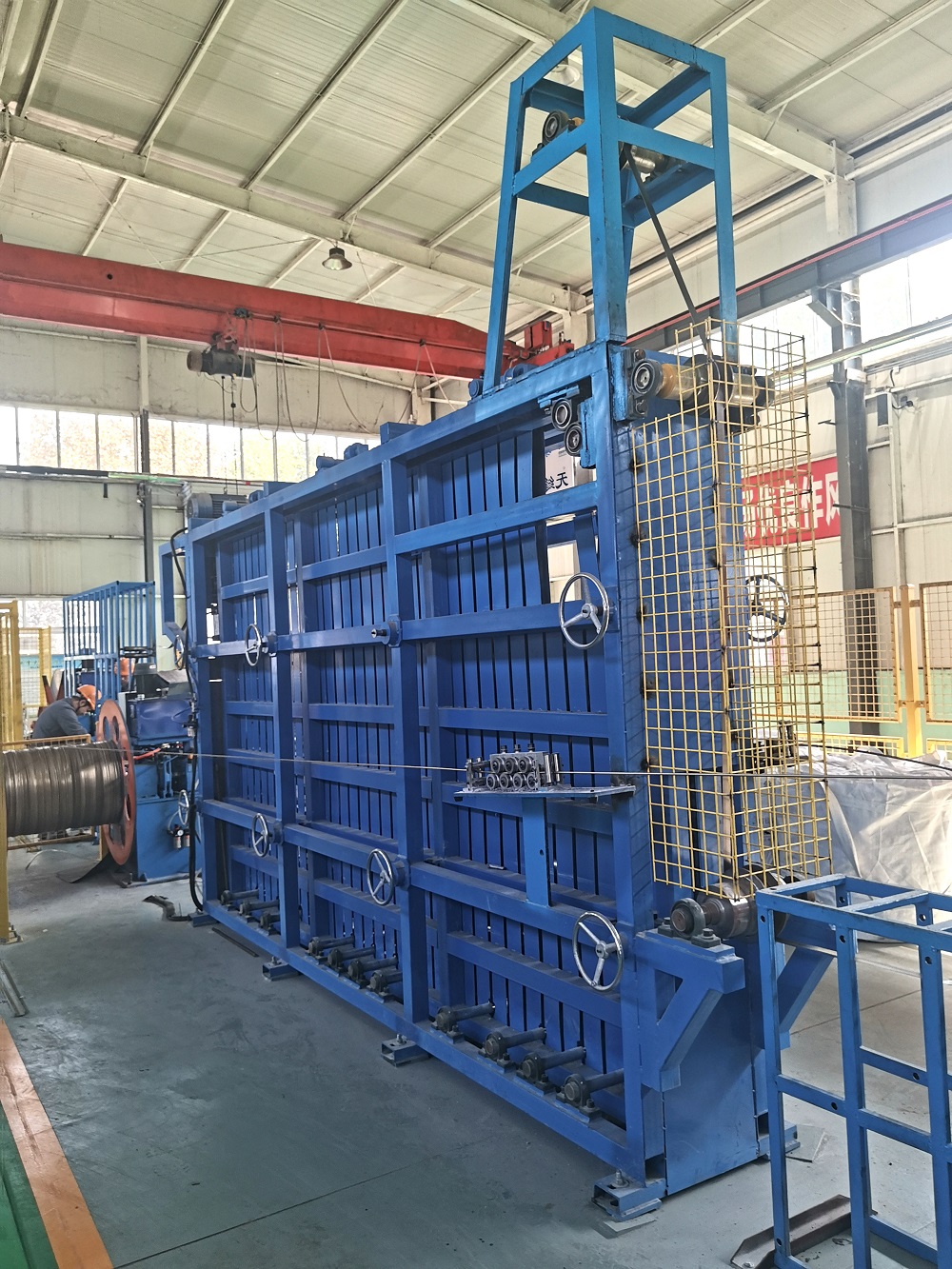
2.1 Vertical Accumulators (Tower Type): These systems utilize a fixed upper roller nest and a movable lower carriage that travels vertically within a tower structure. The strip passes multiple times between the nests. Key advantages: Minimal floor space footprint, excellent for medium to heavy-gauge strip (up to 12.7 mm or more) due to gravity-assisted tension separation. Considerations: Requires significant building height (often 15–25 meters), and the moving mass of the carriage can be substantial, requiring robust hoisting systems.
2.2 Horizontal Accumulators (Cage Type / Rail Type): In this configuration, two nests of rollers—one fixed, one movable on rails—are arranged horizontally. The strip snakes back and forth between them. Key advantages: Lower overall height, easier maintenance access, and very high storage capacities (often exceeding 1000 meters). Particularly well-suited for thin-walled and precision tubing where minimal strip surface marking is critical. The tube mill accumulator designs offered by SANSO include both high-capacity horizontal systems for thin-wall lines and rugged vertical towers for heavy-wall casing mills, ensuring optimal matching to product mix.
2.3 Festoon Accumulators: Simpler, low-cost systems where strip hangs in loose loops (festoons) between rollers. Driven by gravity or low-pressure cylinders. Suitable for lower speed lines (under 60 m/min) and lighter gauges, but limited in storage capacity and tension control precision.
Sizing an accumulator correctly requires a detailed analysis of the production cycle. Under-sizing leads to line stops; over-sizing adds unnecessary capital cost.
The minimum required strip length storage is calculated as: L_min = V_line × T_join. Where V_line is the maximum continuous mill speed (m/min) and T_join is the total time required for the entry section to complete a coil change and weld (typically 60 to 120 seconds). For example, a mill running at 80 m/min with a 90-second join time requires a minimum storage of 120 meters. However, prudent engineering adds a safety margin (typically 15–20%) to account for deceleration/acceleration profiles and unforeseen delays, resulting in a specified capacity of 140–150 meters.
Precise and consistent strip tension is paramount to prevent strip wandering, edge damage, or "telescoping" within the accumulator. Modern systems employ closed-loop control:
Carriage Position Control: The primary loop. The exit bridle pulls strip from the accumulator. The carriage position is monitored, and the entry bridle speed is modulated to maintain the carriage within its operating range (typically 20% to 80% of travel).
Dancer Rollers or Load Cells: Provide fine tension control, especially during acceleration/deceleration. Hydraulic or pneumatic cylinders apply a controlled force to a dancer roller, maintaining constant strip tension regardless of carriage position or strip modulus variations.
Anti-Snaking Guides: Edge guides and rollers prevent lateral strip movement, crucial for maintaining strip alignment into the forming mill.
For critical surface applications (e.g., automotive lines, polished stainless), accumulator rollers must be meticulously designed. Roller diameter must be large enough to prevent strip yielding (typically > 300–400 mm for heavy gauges). Surfaces are often coated with urethane, chrome, or specialized polymers to prevent marking. Each roller should be mounted on precision bearings with minimal runout to avoid inducing vibration into the strip.
The quality and stability of the strip exiting the tube mill accumulator directly affect the welding process and final tube quality.
Weld Stability: Fluctuations in strip tension or speed caused by an unstable accumulator directly translate to variations in the "V" gap opening at the weld box. This can lead to cold welds, penetrators, or inconsistent bead formation. A well-tuned accumulator acts as a mechanical low-pass filter, smoothing out transients from the entry section.
Reduced Scrap Generation: Every start-stop cycle of a tube mill produces a length of off-gauge tube at the head and tail until stable conditions are re-established. By enabling true continuous operation, a properly sized tube mill accumulator from a reliable supplier like SANSO eliminates these transient sections, increasing the overall yield from prime material by 1–3%—a significant margin in high-volume production.
Integration with Downstream Equipment: The accumulator must communicate seamlessly with the line's PLC. During a planned coil join, the entry section signals the accumulator to begin decelerating the entry bridle while the exit bridle continues at speed. Modern systems from SANSO integrate accumulator control with upstream uncoilers, shears, welders, and downstream forming sections, creating a fully synchronized production cell.
To ensure longevity and consistent performance, a proactive maintenance regimen is essential.
Guide Rail and Carriage Alignment: Check and lubricate rails or guide wheels monthly. Misalignment causes uneven roller wear and strip tracking issues.
Tension System Calibration: Calibrate load cells and pressure transducers on dancer systems quarterly to maintain setpoint accuracy of ±1%.
Roller Bearing Inspection: Listen for bearing noise during operation. Replace bearings showing signs of roughness to prevent roller seizure and strip damage.
Sensor and Limit Switch Checks: Verify the functionality of all proximity sensors, limit switches, and encoders that define carriage travel limits and position feedback. Faulty sensors are a common cause of emergency stops.
Q1: What is the typical storage capacity range for a tube mill accumulator?
A1: Capacities vary widely based on line speed and coil change time. Small, low-speed lines may have accumulators storing 50–80 meters. High-speed mills (60–120 m/min) typically require 150–300 meters. Ultra-high-speed lines or those with complex welding requirements can feature accumulators storing 500 meters or more, using horizontal cage designs.
Q2: How does a horizontal accumulator differ from a vertical one in terms of strip threading?
A2: Threading a vertical tower requires the strip to be pulled up through multiple passes, which often necessitates a "threading rope" or chain system to pull the strip through the stationary and moving nests. Horizontal accumulators are generally easier to thread, as the strip path is linear and the movable carriage can be positioned near the entry for direct feeding, reducing setup time during initial line commissioning or after a strip break.
Q3: Can an accumulator handle different strip widths and gauges without adjustment?
A3: Yes, modern accumulators are designed with a wide operating range. Key adjustable features include: 1) Edge guide opening, which can be manually or motor-adjusted to suit strip width. 2) Tension settings, which are programmed via recipes for different gauges and materials. The mechanical structure (roller length, tower height) is designed for the maximum specified strip width.
Q4: What causes strip "telescoping" inside an accumulator and how is it prevented?
A4: Telescoping refers to the strip shifting laterally and piling up against the side frames. It is typically caused by: 1) Incorrect entry or exit strip alignment. 2) Uneven tension across the strip width (e.g., camber in the incoming strip). 3) Worn or misaligned accumulator rollers. Prevention involves rigorous initial alignment, maintaining precise tension control, and using strip edge guides or anti-snaking rolls that gently correct lateral drift.
Q5: How does a tube mill accumulator contribute to energy efficiency?
A5: Primarily by enabling the main mill drive and the high-power welding system (like a solid state high frequency welder) to run continuously at optimal efficiency, avoiding the energy spikes associated with frequent acceleration and deceleration. Additionally, modern accumulators use regenerative drives on the carriage or bridle systems, capturing energy during deceleration and feeding it back into the plant's DC bus or grid.
Q6: What is the typical lifecycle of a well-maintained tube mill accumulator?
A6: With proper maintenance—including regular lubrication, alignment checks, and timely replacement of wear components like roller bearings and guide shoes—the structural and mechanical lifespan of an accumulator can easily exceed 20–25 years. The control system and drives may be upgraded during that period to maintain performance and connectivity with modern line controls.
The tube mill accumulator is far more than a simple strip storage device. It is a sophisticated electro-mechanical system that enables true continuous casting of coil into tube, directly impacting throughput, quality, and yield. Selecting the correct type—vertical, horizontal, or festoon—and sizing it correctly based on rigorous analysis of line speed and join time is a fundamental engineering decision. When integrated seamlessly with the forming mill, welder, and downstream handling equipment (including precision pipe packing machines), a high-performance accumulator from an experienced integrator like SANSO transforms a batch-dependent line into a true continuous-flow manufacturing asset, providing a decisive competitive advantage in the global tube and pipe market.


