In electric resistance welding (ERW) tube production, the consistency of the cooling medium directly determines weld integrity, surface finish, and tooling lifespan. Industrial coolant filtration is not a peripheral utility—it functions as a process control variable with measurable impact on first-pass yield. Contaminants generated during strip forming, edge preparation, and welding range from sub-micron ferrous oxides to larger machining chips. Without precise removal, these particles cause surface defects, accelerate roll wear, and create weld zone inconsistencies that escape nondestructive testing only to manifest in field failures.
This analysis provides a technical framework for specifying and integrating a coolant filtration architecture suited to high-speed tube mills. We examine particle size distribution profiles, filtration media selection criteria, hydraulic circuit design, and the economic rationale for automated contaminant removal. Drawing on field data from installations across carbon steel and stainless steel production lines, we illustrate how properly engineered coolant filtration delivers measurable reductions in tooling costs and unplanned downtime. SANSO applies these engineering principles in turnkey filtration systems tailored to tube and pipe manufacturing environments.
Effective coolant filtration begins with understanding the nature, size distribution, and concentration of particulate matter in the circulating fluid. In a typical tube mill, contaminants originate from three primary zones:
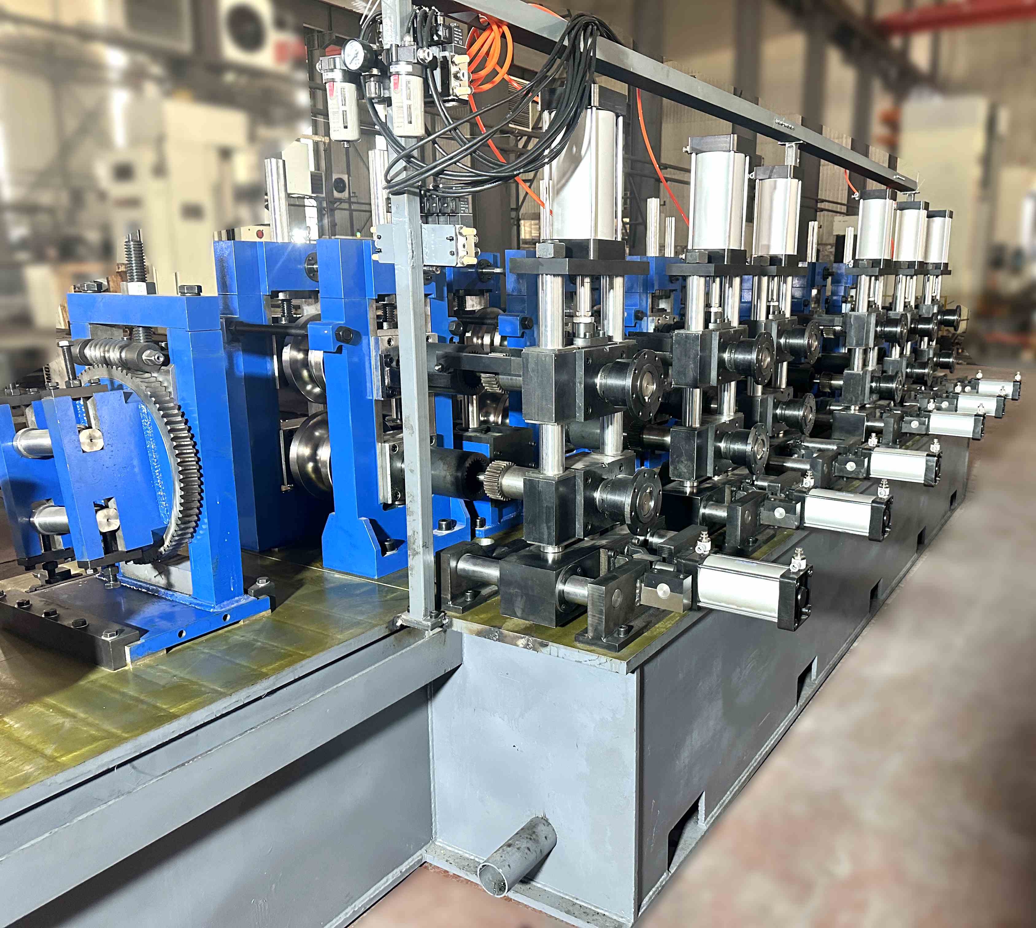
Forming section: As strip passes through forming rolls, edge burrs and roll scale generate ferrous particles ranging from 10 to 500 microns. High-strength steels produce finer, more abrasive particles due to increased work hardening.
Welding zone: At the induction coil or contact shoe interface, localized heating generates metallic oxides and vaporized material that condenses into sub-micron particles (0.5–5 microns). These fine particles are electrically conductive and pose arcing risks.
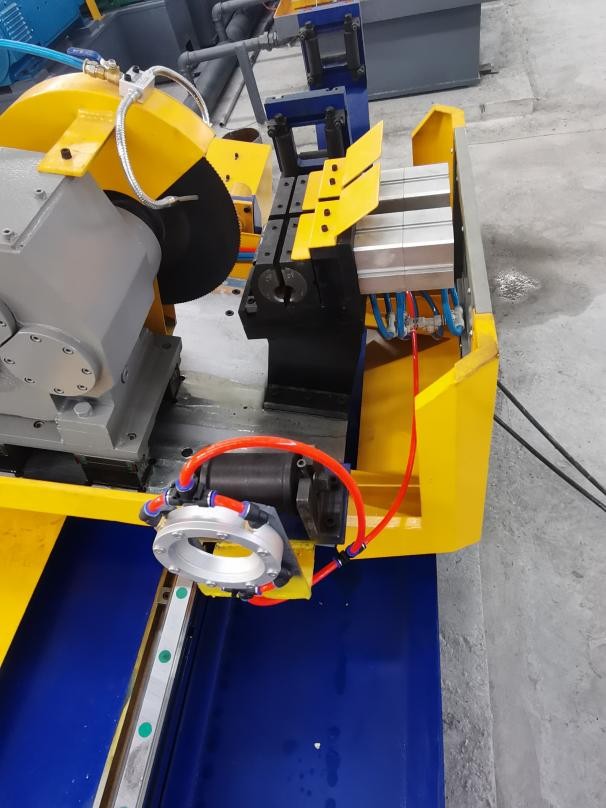
Sizing and scarfing: After welding, the scarfing operation removes the external and internal weld bead, producing larger chips (100–1,000 microns) that settle rapidly but cause abrasion if not immediately removed.
Particle count analysis from 20 tube mill installations reveals average contaminant loading of 120–180 mg/L at the return line to the filtration unit. Without adequate coolant filtration, particle accumulation in the reservoir reaches 500–800 mg/L within 72 hours of operation. At this concentration, the coolant’s lubricity degrades, and the abrasive effect on tungsten carbide rolls increases by a factor of 3–4 based on pin-on-disk wear tests conducted under identical load conditions.
No single coolant filtration technology addresses the full particle size spectrum present in tube mill coolant. Industrial practice employs staged filtration, with each stage optimized for a specific particle size range and contaminant type.
Ferrous particles constitute 70–85% of the total contaminant mass in steel tube production. A magnetic separator positioned at the coolant return removes ferrous material down to 15–20 microns with 90–95% efficiency. For facilities processing stainless steel or non-ferrous alloys, a hydrocyclone bank provides centrifugal separation, removing particles above 40 microns with no consumable media. Integrating either technology as the first stage in a coolant filtration system reduces the solids load on downstream media filters by 50–70%, directly extending media life and reducing labor costs.
Following primary separation, fine filtration removes residual particulates to achieve the cleanliness level required for weld zone stability. Media options include:
Paper bed filters: Indexing roll media with nominal ratings of 20–40 microns. Ideal for high-flow applications with consistent solids loading. Beta ratios (β25) exceeding 200 are achievable with proper media selection.
Depth cartridge filters: Pleated or wound cartridges rated 10–25 microns absolute. Provide higher filtration precision but require more frequent change-outs unless protected by upstream separation.
Self-cleaning screen filters: Stainless steel wedge-wire elements with 50–100 micron retention. Used primarily as pre-filters to protect precision stages from large debris.
For ERW mills producing tube for automotive or pressure applications, a two-stage coolant filtration configuration—magnetic separator followed by 25-micron paper bed—consistently achieves ISO 4406 cleanliness codes of 17/15/12, the threshold recommended by major automotive OEMs for structural tube suppliers.
Properly sized coolant filtration requires balancing flow capacity, reservoir retention time, and pump head pressure. Undersized systems experience rapid differential pressure rise, forcing premature media changes or bypass conditions that compromise filtration. Oversized systems introduce excessive capital cost and may lead to coolant dwell times that promote bacterial growth.
Key design parameters include:
Design flow rate: Typically 1.5 to 2.5 times the average mill coolant demand to accommodate peak loads during scarfing or high-speed operation. For a 150 mm diameter tube mill operating at 60 m/min, design flow of 600–800 L/min is standard.
Reservoir capacity: Minimum retention time of 3 minutes at design flow to allow air release and initial settling. Larger reservoirs (5–8 minutes) improve thermal stability and provide surge capacity during filter change-outs.
Filter housing sizing: Multiple parallel housings allow for online change-out of media without interrupting production. This configuration is standard for continuous-operation mills.
SANSO engineering teams perform site-specific hydraulic analysis, accounting for pipe length, elevation changes, and the pressure drop characteristics of selected filtration stages to ensure pump selection remains within optimal efficiency range.
Facility managers and production engineers consistently identify three recurring challenges related to coolant management in tube mills. Each of these can be systematically addressed through upgraded coolant filtration architecture.
Unplanned downtime for sump cleaning: In mills using simple strainers or batch filtration, solids accumulate in the reservoir, requiring manual cleaning every 200–400 operating hours. Each cleaning event consumes 4–6 hours of labor and halts production. Automated coolant filtration systems with continuous sludge discharge—such as magnetic conveyors or indexed paper beds—eliminate manual sump cleaning as a recurring task, reducing annual downtime by 40–80 hours per line.
Inconsistent weld zone conditions: When filtration efficiency varies with media saturation, the coolant delivered to the welding station shows variable electrical conductivity and cooling capacity. This results in inconsistent heat input, manifested as variations in weld flash geometry and increased reject rates. Closed-loop coolant filtration with differential pressure monitoring and automated media indexing maintains constant fluid cleanliness regardless of upstream contaminant load variations.
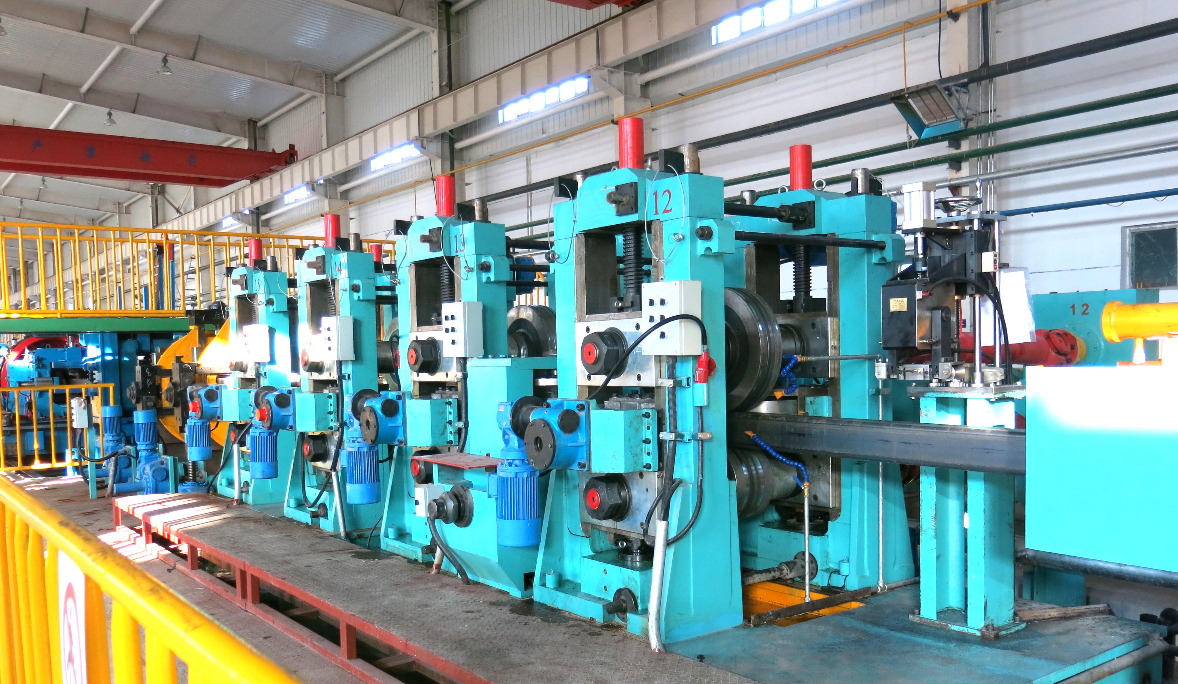
Premature roll wear and tooling replacement: Tungsten carbide forming rolls are susceptible to abrasive wear from particles embedded in the coolant film. Data from a 100 mm tube mill shows that upgrading from 100-micron bag filtration to a 25-micron paper bed system extended roll life from 1,200 to 2,100 operating hours—a 75% increase—with corresponding savings in regrinding costs and changeover downtime.
Modern tube mills increasingly treat coolant filtration as an integrated subsystem within the production line’s control architecture. Key integration points include:
Flow monitoring with mill interlocks: If coolant flow drops below the minimum threshold required for adequate cooling, the mill automatically slows or stops to prevent damage to induction coils or forming tools.
Temperature control: Precision cooling circuits maintain coolant within ±1.5°C of setpoint, critical for consistent weld properties in high-strength low-alloy (HSLA) steels where martensitic formation is temperature-sensitive.
Predictive maintenance: Differential pressure trends across filter stages are logged to SCADA systems, allowing maintenance teams to schedule media changes during planned coil changes rather than as emergency interventions.
SANSO filtration packages are designed with open communication protocols (Modbus TCP, Profinet) to interface with existing mill PLCs, providing real-time status and historical data for continuous improvement initiatives.
The financial case for upgrading coolant filtration in a tube mill operation is built on three quantifiable cost centers.
Tooling and roll maintenance: A typical carbide roll set for a 150 mm tube mill carries a replacement cost of $35,000–$50,000. Extending roll life by 50% through improved filtration yields annual savings of $15,000–$25,000 per roll set. With multiple sets in rotation, total annual savings often exceed $60,000.
Coolant consumption and waste disposal: Central coolant volumes of 2,000–5,000 liters require replacement every 3–6 months when contamination accelerates emulsion breakdown. Advanced coolant filtration extends coolant life to 12–18 months, reducing purchase and disposal costs by $8,000–$15,000 annually per line.
Scrap reduction and yield improvement: For a mill producing 40,000 tons annually, a 0.4% reduction in scrap rate—attributable to improved weld quality and surface finish—represents 160 tons of finished product. At $1,100 per ton, this yields $176,000 in annual value.
Combined, these benefits typically yield a payback period of 8–12 months for a comprehensive coolant filtration upgrade, with ongoing annual cost reductions thereafter.
When specifying a new coolant filtration system or retrofitting existing equipment, engineering teams should request the following technical documentation from suppliers:
ISO 4406 cleanliness certification at design flow, verified by particle count analysis at both filter inlet and outlet.
Beta ratio (βx) for selected media, supported by multi-pass filter testing per ISO 16889.
Maximum allowable differential pressure and corresponding energy consumption curves for the selected pumps.
Construction materials for wetted components (316 stainless steel is standard for synthetic coolant compatibility).
Mean time between failures (MTBF) data for automated components such as indexing drives and motorized valves.
Suppliers with direct tube mill experience, such as SANSO, provide detailed installation drawings, hydraulic calculations, and commissioning support to ensure seamless integration with existing production infrastructure.
Q1: What particle size should a tube mill coolant filtration system target for optimal weld quality?
A1: For ERW processes, particles larger than 25 microns are the primary cause of weld zone arcing and surface defects. A well-designed system should achieve a sustained ISO 4406 code of 17/15/12 or better, meaning fewer than 1,280 particles per milliliter larger than 14 microns, and fewer than 320 particles larger than 21 microns. This typically requires a filtration stage with a nominal rating of 25 microns or finer.
Q2: How often should filter media be changed in a high-volume tube mill?
A2: Media change frequency depends on contaminant load, not fixed time intervals. Systems equipped with differential pressure transmitters signal when media reaches its dirt-holding capacity. For paper bed systems processing carbon steel at 15 tons per shift, typical intervals range from 60 to 120 operating hours. Mills with magnetic pre-filtration often see intervals exceeding 200 hours.
Q3: Can a coolant filtration system eliminate the need for manual sump cleaning?
A3: Systems incorporating continuous sludge removal—such as indexed paper beds with scrapers, magnetic conveyors, or automatic centrifugal separators—remove solids before they settle in the reservoir. With such configurations, manual sump cleaning becomes a semi-annual or annual task rather than a monthly interruption, reducing labor costs and downtime substantially.
Q4: What impact does filtration have on welding electrode and copper shoe life?
A4: Copper forming shoes and induction coil contact surfaces are highly sensitive to particle abrasion and embedment. Data from tube mills equipped with precision coolant filtration show copper shoe life extends by 40–60%, and electrode dressing intervals increase proportionally. The reduction in conductive particle concentration also minimizes stray arcing, which causes pitting on copper surfaces.
Q5: How do I integrate a new filtration system with an existing coolant tank and piping?
A5: Integration typically follows a bypass or full-flow configuration. For retrofit installations, SANSO engineers assess existing tank capacity, pump sizing, and piping layout to determine optimal integration points. Modular filtration skids are available that install between the return line and the clean coolant header, minimizing production disruption. Full integration includes electrical interconnection with the mill’s control system for automated operation and alarm management.
For detailed engineering support, filtration system design, or to request a site-specific proposal for your tube mill operations, consult the technical team at SANSO. Our solutions are engineered for reliability, precision, and measurable production improvement.