In high-frequency induction welding (ERW) and continuous tube milling, the quality of the cooling lubricant directly determines production consistency. A properly engineered coolant filter system is not merely an auxiliary component—it functions as a critical process control element. Contaminants such as ferrous fines, grinding swarf, and oxidation particles accumulate rapidly in closed-loop systems. Without continuous filtration, these particles compromise weld integrity, accelerate roll wear, and increase scrap rates.
Manufacturing operations that process carbon steel, stainless steel, and high-strength alloys require a coolant filter system capable of handling variable contaminant loads while maintaining flow rates above 200 L/min. This analysis outlines the engineering principles behind modern filtration architectures, the economic impact of filtration precision, and how system selection influences total cost of ownership (TCO). We will also examine how SANSO integrates these principles into turnkey solutions for tube and pipe producers.
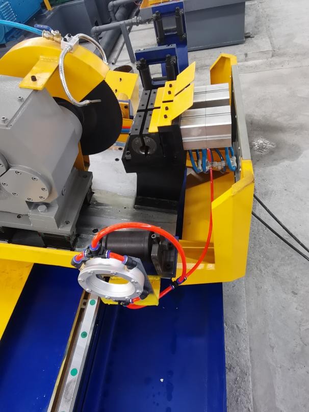
Industrial coolant in tube mills circulates through several high-wear zones: the forming section, welding area (where copper shoes or induction coils contact the strip), and sizing stands. Each zone introduces distinct particulate matter. Ferrous particles generated from strip edges and roll contact range from 5 to 200 microns. If left in suspension, these abrasives create a lapping effect on guide rolls and tungsten carbide forming tools, reducing tool life by up to 40% in documented case studies.
For ERW processes, the presence of conductive particles in the coolant near the welding zone can cause arcing, inconsistent heat input, and internal flash defects. A coolant filter system that cannot achieve a cleanliness rating of NAS 7 or better (per ISO 4406) introduces variability that quality control departments cannot compensate for through downstream testing alone. Common failure modes observed in under-filtered systems include:
Increased surface roughness on finished tube OD/ID, requiring secondary finishing.
Premature failure of carbide rolls due to micro-abrasion and particle embedment.
Clogged nozzles and uneven coolant distribution, leading to localized overheating.
Bacterial growth in stagnant areas, degrading coolant chemistry and causing odor.
No single technology addresses all contaminant types effectively. A robust coolant filter system for tube mill applications typically integrates multiple stages. Selection depends on flow rate, particle size distribution, and the specific metallurgy being processed.
Ferrous particles constitute the majority of debris in steel tube production. Permanent magnetic separators positioned upstream of the primary filter remove 85–95% of ferrous contaminants down to 20 microns. This reduces the load on downstream media filters and extends their service intervals. For high-production mills processing over 15 tons per shift, a heavy-duty magnetic drum separator with automatic cleaning is standard.
Disposable media filters—either roll-type paper bed or depth cartridges—provide the fine filtration necessary for weld zone cleanliness. A well-designed coolant filter system employing 25-micron nominal paper achieves a Beta ratio (β25) of 200 or higher, meaning only 0.5% of particles above 25 microns pass through. Paper bed systems are preferred for high-solids-loading applications due to their continuous indexing mechanism and lower maintenance labor requirements.
For operations with high volumes of heavy sludge (such as after the scarfing process), a hydrocyclone pre-filter removes dense particles down to 40–50 microns without consumable media. When integrated as the first stage in a coolant filter system, hydrocyclones reduce media consumption by 30–50% while protecting precision downstream filters from premature blinding.
Sizing a coolant filter system requires accurate determination of both flow rate and contaminant mass loading. Under-sizing results in rapid differential pressure rise, frequent media changes, and unscheduled production stops. Over-sizing adds unnecessary capital cost and may lead to coolant dwell time that promotes biological growth. Critical parameters include:
Peak flow demand: Calculated from pump output, nozzle count, and line size. Typical tube mill systems require 400–1,200 L/min.
Contaminant generation rate: Derived from material removal rates and mill speed. For example, a 100 mm OD tube line at 50 m/min generates 8–12 kg of fine particulate per shift.
Reservoir capacity: Should provide 3–5 minutes of retention time at maximum flow to allow for settling and aeration.
Advanced systems from SANSO incorporate variable-frequency-driven pumps and automated differential pressure monitoring. These features enable real-time adjustment of filtration rates based on actual contamination levels, rather than fixed intervals, optimizing both energy consumption and media life.
Operations managers in tube and pipe manufacturing consistently report three primary challenges related to coolant management:
Unplanned downtime for cleaning: In systems without automated sludge removal, manual cleaning of tanks and filter housings requires 4–8 hours of downtime every 2–4 weeks. For a continuous mill running three shifts, this represents 2–3% of total production capacity lost annually.
Inconsistent filtration performance: Many facilities rely on disposable bag filters that are changed based on calendar days rather than actual differential pressure. This leads to periods of under-filtration (when bags are saturated) and wasted media (when changed prematurely).
Coolant degradation and disposal costs: When particulate load exceeds 0.5% by volume, the coolant’s emulsification stability breaks down. Frequent coolant replacement increases disposal costs and environmental compliance burdens.
These pain points are directly addressed by adopting a centralized coolant filter system with automated backwashing, continuous sludge discharge, and real-time particle monitoring. Facilities that have transitioned from standalone machine filters to centralized systems report a 60–70% reduction in coolant-related downtime and a 50% extension in tool life.
Modern tube mills increasingly adopt Industry 4.0 principles, where the coolant filter system communicates with the main production PLC. Key integration points include:
Flow interlocks that prevent mill start-up if coolant flow falls below minimum threshold.
Temperature control loops that maintain coolant within ±2°C of setpoint, critical for consistent weld properties in high-strength steels.
Predictive maintenance alerts based on filter differential pressure trends, allowing media changes to be scheduled during planned coil changes rather than as emergency interventions.
SANSO engineers filtration packages that integrate seamlessly with existing mill control architectures, providing both standalone HMI interfaces and full remote monitoring capabilities through SCADA systems.
Quantifying the return on investment for a high-performance coolant filter system requires evaluating three cost centers:
Tooling and roll costs: In a typical 100 mm tube mill, carbide roll sets cost $25,000–$40,000 per set. Extending roll life from 12 months to 18 months through improved filtration yields annual savings of $8,000–$13,000 per roll set, with multiple sets in rotation.
Coolant consumption and disposal: A 1,200 L coolant system that requires change-out every 3 months due to contamination costs approximately $8,000 annually in coolant purchase and disposal fees. With sub-micron filtration extending coolant life to 12–18 months, annual costs drop by 60–70%.
Scrap reduction: For a mill producing 30,000 tons annually, a 0.5% reduction in scrap rate (attributable to fewer weld defects and surface imperfections) translates to 150 tons of finished product saved. At $1,200 per ton, this represents $180,000 in additional revenue or cost avoidance.
When these factors are combined, the payback period for a comprehensive coolant filter system typically falls between 8 and 14 months for high-volume tube mills.
When specifying a new coolant filter system or upgrading existing equipment, engineering and procurement teams should request the following technical documentation from suppliers:
ISO 4406 cleanliness level achievable at design flow, verified by particle count analysis.
Beta ratio (βx) for the selected media, along with multi-pass test results (ISO 16889).
Maximum allowable pressure drop at end-of-life, and corresponding energy consumption curves.
Materials of construction for wetted parts (316 stainless steel is preferred for corrosion resistance and compatibility with synthetic coolants).
Mean time between failures (MTBF) data for moving components such as indexing mechanisms and motorized valves.
Suppliers with direct experience in tube mill environments, such as SANSO, will also provide site-specific recommendations based on mill speed, material width, and production scheduling patterns.
Q1: What is the optimal filtration micron rating for an ERW tube mill
coolant filter system?
A1: For ERW applications where weld quality
is paramount, a nominal filtration rating of 25 microns (absolute rating of
40–50 microns) is the industry standard. If the mill processes high-strength or
stainless steels requiring superior surface finish, a secondary polishing filter
with 10-micron absolute rating is recommended downstream of the primary unit.
The key is to achieve a sustained ISO 4406 cleanliness code of 18/16/13 or
better.
Q2: How often should filter media be changed in a high-production
tube mill?
A2: Media change intervals depend on contaminant load,
not calendar time. A properly designed coolant filter system includes
differential pressure gauges or transmitters that signal when media reaches its
dirt-holding capacity. For paper bed systems in mills processing carbon steel,
typical intervals range from 40 to 120 operating hours. For magnetic drum
separators with automatic cleaning, media life extends substantially.
Q3: Can a coolant filter system reduce the frequency of sump
cleaning?
A3: Yes. Systems equipped with continuous sludge
discharge—such as drag-out conveyors, automatic magnetic separators, or
centrifugal concentrators—remove solids from the coolant loop before they settle
in the tank. With such features, sump cleaning intervals extend from monthly to
once or twice per year, significantly reducing labor costs and downtime.
Q4: What is the impact of filtration on welding electrode and copper
shoe life?
A4: Copper forming shoes and electrodes are highly
sensitive to particulate contamination. Ferrous particles embed in the copper
surface, creating localized hotspots and accelerating wear. Data from tube mills
using advanced coolant filter systems show copper shoe life increases by 30–50%,
and electrode dressings become less frequent, directly improving line
uptime.
Q5: How do I integrate a new coolant filter system with my existing
central coolant tank?
A5: Integration typically involves bypass or
full-flow plumbing, depending on the system design. For retrofit projects, SANSO
engineers perform on-site assessments to determine optimal pump sizing, piping
layout, and electrical integration. Modular systems are available that install
between the existing return line and the clean coolant header, minimizing
disruption to production.
For detailed engineering support or to request a site-specific proposal for your tube mill operations, consult the filtration specialists at SANSO. Our designs prioritize uptime, filtration precision, and total cost of ownership.