In high‑speed ERW tube and pipe mills, the quality of coolant directly affects weld integrity, tool life, and surface finish. Contaminated coolant—carrying ferrous particles, abrasive grit, and residual lubricants—leads to increased roller wear, inconsistent weld penetration, and higher rejection rates. A properly designed machine coolant filtration system removes solid contaminants to specified micron levels, stabilizes fluid chemistry, and extends coolant service life. This article provides a technical assessment of machine coolant filtration for tube forming and welding applications, covering filtration technologies, contaminant analysis, system sizing, and maintenance protocols. SANSO integrates central coolant filtration systems into its complete tube mill lines, ensuring consistent cooling and lubrication.
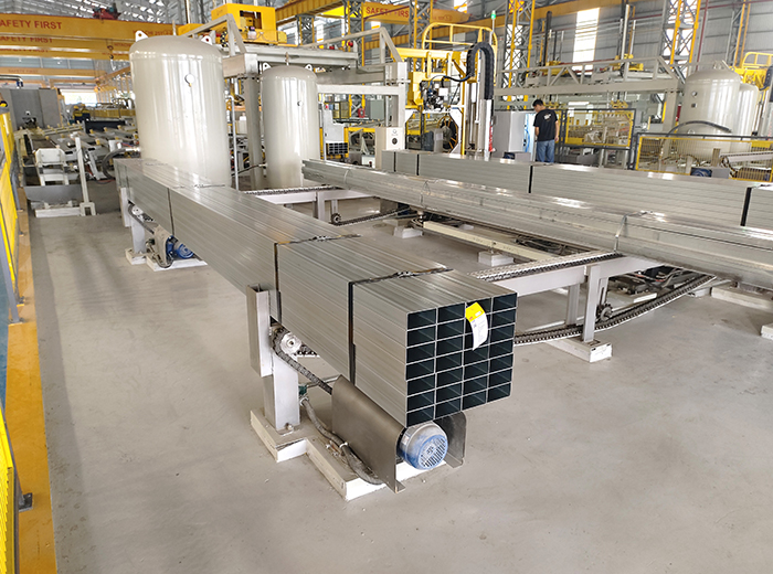
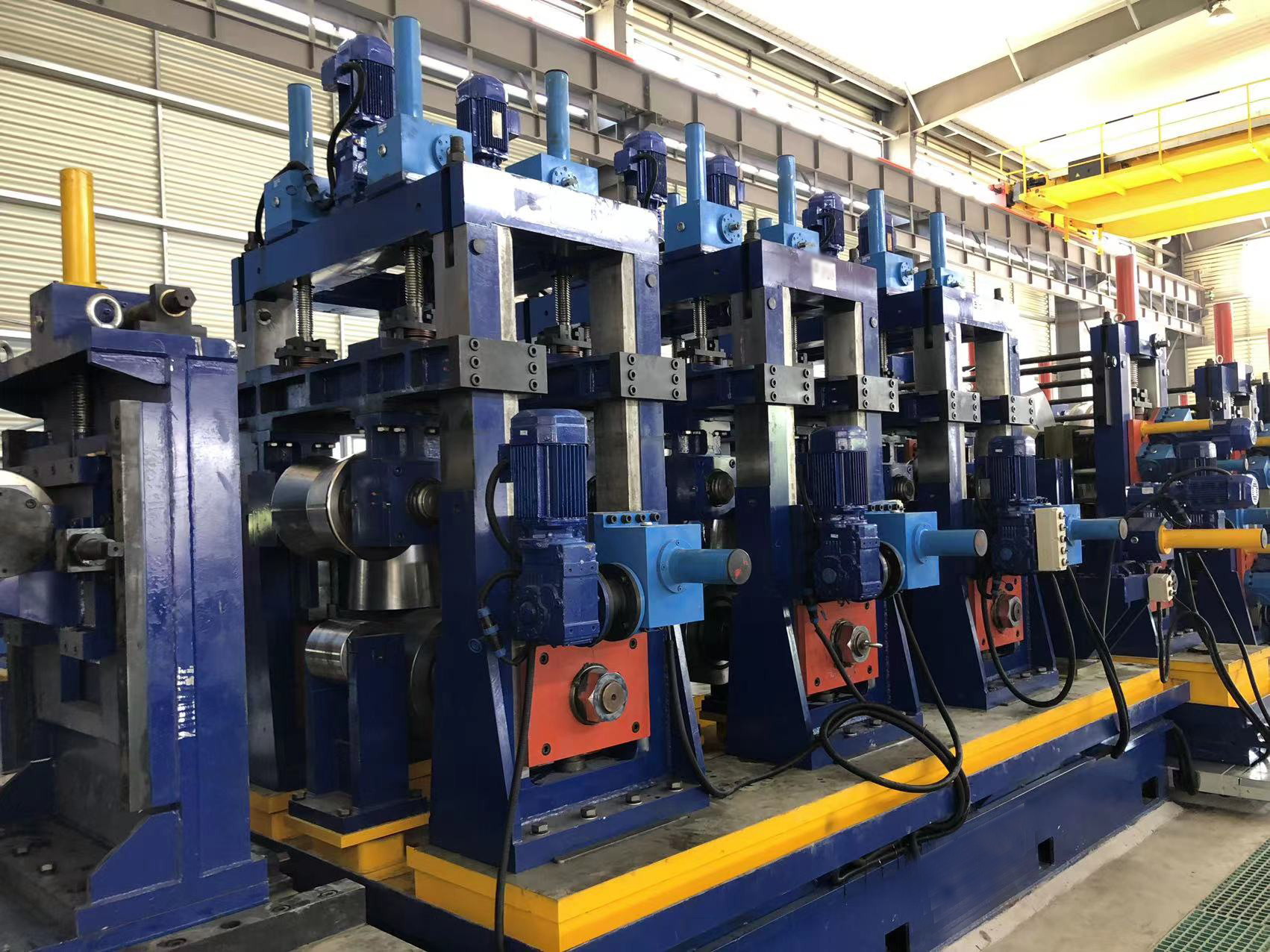
Coolant in a tube mill circulates through the forming section (roller stands), the weld box (HF contact tips and impedance), and the sizing section. Each area introduces specific contaminants that machine coolant filtration must address.
Primary contaminant categories:
Ferrous particles (50‑500 µm): Generated from strip edge shearing, roller wear, and weld bead trimming. These abrasive particles accelerate roller bearing failure and scratch the tube surface. Without filtration, ferrous sludge accumulates in sumps, reducing heat transfer.
Non‑ferrous grit (10‑100 µm): Silica scale from hot‑rolled strip, dust from floor, and residual sand from descaling. Causes polishing marks on tube exterior and increases weld contact tip erosion.
Organic tramp oils (hydraulic leaks, lubricants): Incompatible with water‑based coolants, leading to bacterial growth, foul odors, and reduced cooling efficiency.
Welding fume residues (submicron particles): Oxides of iron and alloying elements (chromium, nickel) that remain suspended and cause contact tip arcing.
Quantitative impact: A tube mill processing 200 t/day with no machine coolant filtration typically accumulates 15‑25 kg of ferrous sludge per shift. Roller life drops from 800 hours to 350 hours; coolant replacement frequency increases from 6 months to 6 weeks. Implementing a filtration system with 25 µm absolute rating reduces sludge generation by 90% and doubles roller life.
Selecting the correct machine coolant filtration technology depends on flow rate, particle size distribution, and coolant type (synthetic, semi‑synthetic, or soluble oil).
For ferrous particle removal, permanent magnetic drums or magnetic belt separators achieve 95‑98% capture of particles >30 µm. Installed directly at the coolant return line, they reduce load on downstream filters. Typical magnetic strength: 2,500‑3,500 Gauss. Maintenance: manual or automatic scraper to remove collected sludge.
Used as a low‑cost primary stage for larger particles (>100 µm). Coolant flows through a series of baffles; heavy particles settle to a drag chain or screw conveyor. Suitable for flow rates up to 500 L/min. Efficiency: 60‑70% for particles >150 µm. Not sufficient as standalone machine coolant filtration for precision welding.
Disposable media (paper, polyester, or cellulose) captures particles down to 10‑25 µm absolute. Two common designs:
Vacuum drum filter: Coolant is drawn through a rotating drum covered with filter paper. Automatic indexing advances the paper when pressure drop increases. Typical filtration area: 2‑10 m². Achieves 25 µm nominal, 40 µm absolute.
Pressure filter (bag or cartridge): Used for finer polishing (5‑10 µm) after media filtration. Higher operating pressure (2‑4 bar) allows compact footprint.
No consumable media; uses centrifugal force to spin particles out of the fluid stream. Effective for particles >20 µm and specific gravity >2.0 (e.g., ferrous, sand). Efficiency curve: 90% at 40 µm, 60% at 20 µm. Ideal as a pre‑filter before media filters. Requires cleanout of sludge pot every shift.
For organic tramp oils, belt skimmers or disc skimmers remove floating
hydrocarbons. For emulsified tramp oils (difficult to separate), use
ultrafiltration (UF) membranes (0.01‑0.1 µm) – though capital cost is high. Many
tube mills combine skimming with weekly biocide dosing. SANSO offers modular filtration stations that
integrate magnetic separation, hydrocyclone, and media filtration in a single
package, sized to match the mill's coolant pump capacity. Proper sizing of machine coolant filtration requires three inputs:
coolant flow rate (L/min), target cleanliness level (ISO 4406 code), and
particle size distribution from a fluid sample. Typical coolant demand for tube mills: Forming section: 0.5‑1.0 L/min per mm of strip width (e.g., 200 mm wide
strip → 100‑200 L/min). Weld box: 30‑50 L/min for contact tip cooling and impedance flushing. Sizing and straightening: 50‑100 L/min. Total pump capacity: 200‑500 L/min for a mid‑size mill (50‑100 mm tube
OD). Filtration system should handle 1.5x the nominal flow to allow for media
blinding. Based on ISO 4406:1999 (particle count per mL): Typical unfiltered coolant: 22/19/13 (meaning >4 µm: 20,000 particles/mL;
>6 µm: 2,500; >14 µm: 160). Target for tube mill weld quality: 16/14/11 (>4 µm: 1,300; >6 µm: 250;
>14 µm: 30). Required filter rating: 25 µm absolute (β25 ≥ 200). Calculate expected sludge generation: For a mill processing 10 t/hour of 2 mm
thick strip, typical wear particle generation is 0.1‑0.3 g per ton of steel. Add
scale from strip (0.5‑1 g/ton). Total sludge: 0.6‑1.3 kg/hour. Filtration system
should have sludge holding capacity for at least 8 hours of continuous operation
(5‑10 kg). SANSO provides a coolant filtration sizing worksheet,
including pump head calculations and tank volume requirements. Even with well‑designed machine coolant filtration, tube mills face specific
operational issues. Below are root causes and corrective actions. Problem: Filter paper clogs within 1‑2 hours instead of 8‑12
hours. Root cause: High concentration of fine particles
(<10 µm) or sticky tramp oil. Solution: Install a
hydrocyclone upstream to remove 40% of fines; add an oil skimmer to reduce tramp
oil content below 1% by volume. Switch to depth filter media (cellulose +
polyester) with higher dirt holding capacity. Problem: Sour smell, pH drop, and corrosion on tube surface.
Root cause: Stagnant zones in filtration tank and tramp oil
providing food for bacteria. Solution: Design tank with sloping
bottom and no dead corners; install an aeration diffuser (maintain dissolved
oxygen >2 ppm); dose biocide weekly (e.g., triazine at 500 ppm). Maintain
coolant pH between 8.5‑9.5. Problem: Magnetic drum fails to capture all ferrous fines;
sludge builds up on downstream media. Root cause: Flow rate
exceeds magnetic separator capacity (max 300 L/min for standard drum).
Solution: Install two parallel magnetic separators or upgrade
to a high‑intensity rare earth magnet (5,000 Gauss) with larger drum
diameter. Problem: Coolant returning at >45 °C reduces lubricity
and accelerates bacterial growth. Root cause: Insufficient tank
volume for cooling (residence time <2 minutes). Solution: Increase tank capacity to achieve 5‑10 minutes residence time; add a plate heat
exchanger with cooling tower water. For every 10 °C reduction in coolant
temperature, filter media life extends by 30%. To sustain performance, machine coolant filtration requires scheduled
maintenance. Below is a recommended weekly and monthly checklist. Daily (operator): Check filter media feed; ensure no
bypass; record pressure drop across filters (replace when ΔP reaches 1.5 bar).
Inspect magnetic drum scraper; clean sludge bin. Weekly (maintenance): Sample coolant for particle count
(ISO 4406) and pH; adjust biocide if needed. Clean hydrocyclone apex nozzle;
inspect for wear. Check belt skimmer tension. Monthly: Drain and clean filtration tank (remove bottom
sludge). Inspect pump impeller for erosion. Replace filter housing gaskets if
leaking. Quarterly: Send coolant sample for full analysis
(viscosity, corrosion inhibition, bacterial count). Calibrate pressure gauges
and flow meters. SANSO supplies filtration systems with remote
pressure monitoring and automatic media advance, reducing manual
intervention. A case study from a tube mill producing 40,000 tons/year of API 5L pipe
compared 12 months without dedicated machine coolant filtration to 12 months with a
three‑stage system (magnetic + hydrocyclone + 25 µm media). Coolant concentrate consumption: Reduced from 4,500 L/year
to 1,800 L/year (saving $13,500). Roller and tooling costs: Forming roller replacement
interval extended from 600 hours to 1,200 hours – annual saving $22,000. Weld contact tip life: Increased from 40 hours to 110 hours
– saving $8,000/year. Rejection rate due to surface defects: Dropped from 2.8% to
0.7% – saving $84,000 in scrap and rework. Filtration system operating cost (media, electricity,
maintenance): $18,000/year. Net annual saving: $109,500. System payback: 5
months. Additionally, the mill achieved cleaner working environment and reduced
hazardous waste disposal fees for spent coolant. Q1: What is the difference between nominal and absolute filter
ratings for coolant filtration? Q2: Can I use the same filtration system for both water‑based
coolants and neat oils? Q3: How often should I replace the entire coolant charge in a tube
mill? Q4: What is the typical pressure drop across a 25 µm absolute filter
element? Q5: Can I retrofit an existing coolant tank with a filtration
system? Q6: How do I dispose of used filter media and collected
sludge? Every tube mill has unique coolant chemistry, flow demands, and space
constraints. A generic filter cart may not address your specific particle size
distribution or tramp oil issues. SANSO offers a structured technical engagement for
coolant optimization: Fluid sampling: Send 1‑liter samples of your used coolant
(before and after existing filtration). We analyze particle count (ISO 4406),
viscosity, pH, and bacterial load. Flow measurement: Our engineer measures pump flow and
return line pressure at your facility. System design: We propose a multi‑stage machine coolant filtration layout, including tank
modifications if needed. ROI projection: Detailed calculation of payback based on
your current coolant consumption, tooling costs, and rejection rates. Implementation and training: Supply and install the system,
train your operators on maintenance protocols. Contact our fluid engineering team directly via the website. Provide your
mill specifications (tube size range, line speed, coolant type) and a brief
description of current contamination issues. We will respond within 24 hours
with a preliminary assessment and a schedule for a free on‑site coolant
audit. Send your coolant filtration requirements to SANSO’s fluid
specialists — include coolant type, flow rate, and current filter change
frequency for a prioritized engineering review.3. Sizing a Coolant Filtration System for Your Tube Mill
3.1 Flow Rate Determination
3.2 Target Cleanliness Levels
3.3 Sludge Holding Capacity
4. Technical Challenges and Solutions in Coolant Filtration
4.1 Premature Filter Media Blinding
4.2 Bacterial Growth and Coolant Degradation
4.3 Magnetic Separator Overload
4.4 Coolant Temperature Rise
5. Maintenance Protocols for Coolant Filtration Systems
6. Economic Benefits of Proper Coolant Filtration
Frequently Asked Questions (B2B Machine Coolant Filtration)
A1: Nominal rating
(e.g., 25 µm nominal) means the filter captures 85‑90% of particles of that size
under lab conditions. Absolute rating (e.g., 25 µm absolute, β25 ≥ 200) means
99.5% of particles at that size are captured. For tube mill weld quality,
specify absolute rating. Machine coolant filtration systems for precision
applications should use absolute‑rated media.
A2: No. Water‑based
coolants require media that is hydrophilic and resistant to bacteria. Neat oils
(straight oils) require hydrophobic media and different viscosity handling.
Filtration hardware (pumps, seals, tanks) also differs: water‑based systems use
stainless steel; oil systems use carbon steel. Never mix applications without
replacing media and cleaning the tank thoroughly.
A3: With effective machine coolant filtration and proper biocide
treatment, water‑based coolants can last 12‑18 months. Replace when pH drops
below 8.0, bacterial count exceeds 10⁵ CFU/mL, or corrosion inhibitor
concentration falls below 50% of fresh mix. Send a sample to a lab every 3
months for total dissolved solids (TDS) – if TDS exceeds twice the fresh mix
value, replacement is recommended.
A4: For clean element at nominal flow
(e.g., 300 L/min), pressure drop is 0.2‑0.3 bar. As particles load, drop
increases. Replace element when differential pressure reaches 1.2‑1.5 bar, or
when flow rate drops by 20%. High pressure drops can starve the coolant pump and
cause cavitation.
A5: Yes. Most existing tanks can be
modified by adding a side‑stream filtration loop (pump + filter housing) or
installing an in‑tank filter module (e.g., vacuum drum mounted above the tank).
SANSO offers retrofit kits that include pump,
magnetic separator, and media filter, with installation typically completed in 2
days.
A6: Used filter paper containing ferrous
sludge may be classified as non‑hazardous waste if coolant is water‑based
without biocides. However, many jurisdictions require testing for oil content
(TCLP). Options: (1) Centrifuge the sludge to recover coolant and compact solids
for recycling to steel mills; (2) Contract with a waste management company for
incineration. Machine coolant filtration systems that
reduce sludge volume by 80% lower disposal costs significantly.Request a Coolant Filtration Audit for Your Tube Mill


