In continuous strip processing lines, the transition between finishing coils represents a period of high risk for production disruptions. The Coil Accumulator serves as the essential buffer that decouples the entry section from the downstream forming mill. Unlike simple strip storage, modern coil accumulator systems manage complex dynamics of mass flow, tension gradients, and material tracking to ensure that the welding section never sees a gap in material feed. This article examines the engineering specifications, control philosophies, and integration strategies required to optimize accumulator performance, with reference to solutions engineered by SANSO for high-speed tube and pipe applications.
The fundamental purpose of a Coil Accumulator is to store sufficient strip to keep the mill running during the longest planned interruption at the entry end. The required storage length (Lacc) is a function of mill exit speed (Vmill) and the total stop time for coil change and welding (Tstop).
Lacc = Vmill × Tstop × Sf, where Sf is a safety factor (typically 1.1 to 1.2). For a mill running at 60 m/min with a 90-second coil change cycle, the accumulator must provide 90 meters of usable strip. However, engineers must distinguish between gross structural capacity and usable capacity. The first and last loops in a horizontal Coil Accumulator often cannot be fully extracted due to carriage limits, meaning the physical length of the accumulator must be oversized by 10-15% relative to the theoretical calculation.
The choice between vertical and horizontal architecture depends on material properties, available plant space, and required tension precision.
Vertical accumulators utilize a fixed sheave stack at the top and a moving carriage at the bottom. Strip tension is generated by the weight of the carriage, often augmented by pneumatic or hydraulic cylinders. This design excels for lighter-gauge materials (0.3–3.0 mm) where precise, low-tension control is required to prevent stretching. The vertical orientation minimizes floor space but requires substantial overhead clearance (often 15–25 meters). Optical sensors monitor the carriage position to regulate bridle speeds.
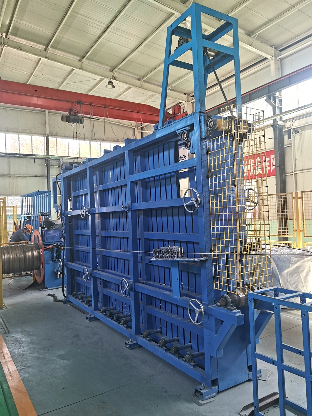
For heavy-gauge strips (>3.0 mm) and high-strength steels, horizontal accumulators are preferred. A moving trolley traverses along rails, with strip threaded between stationary and moving roll nests. The absence of gravitational height limits strip width and thickness. Tension is applied through bridle rolls at the entry and exit, allowing precise control even for materials up to 12.7 mm thick. The primary trade-off is the large footprint, which can exceed 40 meters in length. SANSO offers modular horizontal accumulator designs that allow for future capacity expansion by extending track length without replacing the entire mechanical core.
A sophisticated Coil Accumulator is divided into distinct tension zones. The entry bridle pulls strip from the uncoiler and feeds it into the accumulator. It must overcome the back-tension from the uncoiler and establish a stable strip entry. Inside the accumulator, tension is maintained at a lower level (typically 30-50% of forming tension) to prevent edge wave or center buckle. The exit bridle then pulls strip out of the accumulator and delivers it to the forming mill at the required tension for welding.
Modern control systems use individual DC or AC drives on each bridle roll, with load cells mounted on deflector rolls to provide closed-loop feedback. Tension transitions during carriage reversal are the most challenging—when the carriage changes direction from "filling" to "emptying," the inertia of the strip mass can cause tension spikes unless the drives are synchronized within milliseconds. Direct torque control (DTC) algorithms are now standard to handle these transients.
In a multi-loop Coil Accumulator, strip tracking is inherently unstable due to the cumulative effect of roll misalignment. Even a 0.1-degree skew in a single roll can cause the strip to drift laterally by several centimeters over 100 meters of accumulated length. This drift leads to edge contact with side plates, causing burrs that can later crack during roll forming.
Solutions include crowned rolls in the fixed nests to self-center the strip, and active steering rolls (typically hydraulic) that adjust based on edge sensor feedback. For horizontal accumulators, linear guides on the moving trolley must maintain parallelism within ±1 mm over the entire travel length. Preventative maintenance programs should include laser alignment checks during scheduled downtimes.
The Coil Accumulator does not operate in isolation; it is the central link between the welder and the mill. The accumulator control system must communicate with the shear-welder PLC to anticipate stop events. When the entry section decelerates for the weld, the accumulator begins paying out at an increasing rate. Conversely, after welding, the entry bridle accelerates to refill the accumulator while the mill continues at constant speed.
The key performance indicator here is "recharge time ratio"—the time required to fully refill the accumulator divided by the time it took to empty it. A ratio below 1.0 (e.g., emptying in 90 seconds, refilling in 60 seconds) ensures that the accumulator is always ready for consecutive coil changes. This requires the entry drive system to have higher speed capability than the exit drive, often 120-150% of nominal mill speed. Advanced systems from manufacturers like SANSO incorporate predictive algorithms that adjust recharge speed based on the incoming coil OD and remaining strip length.
Different strip grades impose unique demands on accumulator design:
High-Strength Steels (AHSS, DP, TRIP): These materials have high springback and require larger roll diameters (typically >600 mm) to prevent permanent deformation around sheaves. Higher tensions are also needed to flatten the strip before entry.
Stainless Steel: Surface protection is paramount. Rolls must be polished or coated (e.g., with tungsten carbide) to prevent pick-up. Vertical accumulators are often favored to minimize contact points.
Aluminum and Copper: Soft materials are prone to scratching and marking. Tension levels must be kept low (often <5 MPa), and roll surfaces should be non-marring, such as polyurethane or rubber-covered.
The modern Coil Accumulator is a rich source of operational data. Encoders on the moving carriage provide real-time strip inventory. Vibration sensors on sheave bearings detect incipient failures before they cause unscheduled downtime. By analyzing trends in carriage acceleration and deceleration, maintenance teams can identify degradation in drive system performance or increased friction in the trolley wheels.
Integration with higher-level MES (Manufacturing Execution Systems) allows the accumulator to act as a buffer not just for material, but for information. When a coil with known surface defects is processed, the accumulator can be programmed to isolate that section, allowing operators to mark or remove it offline without stopping the mill. This level of intelligence transforms the accumulator from a passive storage device into an active quality management tool.
A1: A looping pit relies on gravity to form a free loop, offering minimal tension control and limited storage length. A Coil Accumulator uses structured roll nests and bridles to provide precise tension regulation, higher storage density, and the ability to handle a wide range of material thicknesses without loop sag or twist.
A2: Horizontal accumulators can store from 100 meters up to over 1000 meters of strip, depending on the number of passes (strip strands) and the track length. For example, a 12-strand accumulator with a 50-meter track provides 600 meters of storage. The limit is practical—very long accumulators require careful synchronization of multiple trolleys.
A3: Yes, but it requires a civil engineering assessment. Horizontal accumulators need a flat, level foundation capable of supporting the trolley and strip weight. Vertical accumulators require structural steel modifications to support the top sheave assembly. SANSO specializes in retrofit projects, often reusing existing bridle drives while extending the storage track.
A4: Wrinkling is typically caused by excessive compression stress. Check if entry tension is too high relative to strip thickness, causing buckling as the strip enters the first fixed roll. Also, inspect roll parallelism—misalignment can force the strip to travel unevenly, creating slack edges. Reducing accumulator tension setpoint or increasing roll crown often resolves the issue.
A5: For 24/7 operation, greasing intervals for sheave bearings should be every 500–1000 operating hours, depending on bearing size and speed. Vibration analysis should be performed monthly to detect early-stage spalling. Thermography can also identify bearings running hot due to over-greasing or misalignment.
A6: Width determines the roll face length and the required structural rigidity. Wider strips (e.g., >1500 mm) require larger diameter rolls to minimize deflection under load. Deflection must be kept below 0.5 mm per meter of width to maintain even tension distribution across the strip.
In conclusion, selecting and sizing a Coil Accumulator demands a rigorous engineering approach that considers process parameters, material properties, and long-term reliability. Systems engineered by SANSO demonstrate how integrating robust mechanical design with advanced control algorithms maximizes overall equipment effectiveness (OEE) in continuous tube and pipe production.