Every production manager in the ERW pipe industry faces the same dilemma. You
want to push your roll forming tube mill faster. Higher speed means more tons
per shift and a direct drop in unit cost. But the moment you dial up the
frequency drive, weld defects start to appear. Cold welds. Slag inclusions.
Excessive burr. Fusion failures. The reject pile grows, and the supposed gain
from higher speed vanishes in rework costs.
At SANSO, we have spent over two decades building complete roll forming tube
mill lines. We have learned that speed optimization is not a simple matter of
turning a dial. It is a systematic engineering challenge. It requires matching
mechanical rigidity, tooling precision, and high-frequency energy in a carefully
balanced way. When done correctly, you can achieve a 15-20% improvement in
overall energy efficiency while keeping weld quality acceptance rates above
99.2%. This article walks through the physics, the practical steps, and the
real-world results.
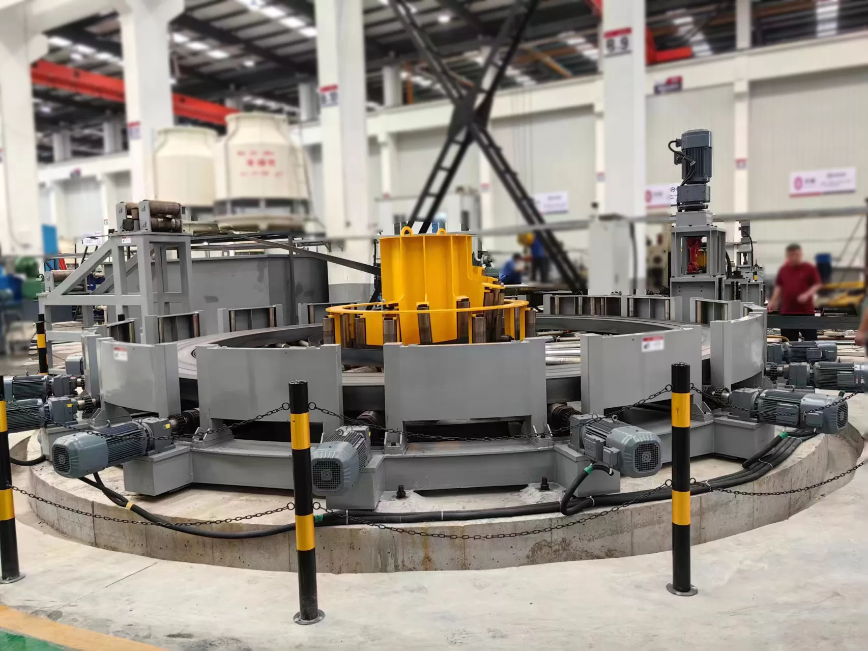
The Physical Logic Behind Speed and Weld Quality
Before touching any control panel, you must understand what changes inside
the roll forming tube mill when speed increases. Three fundamental interactions
occur.
Heat input versus time. The faster the strip travels, the
less time it spends in the V-shaped opening zone where the high-frequency
current does its work. If the HF power stays constant, the material receives
less energy per unit length. The edges do not reach proper forging temperature.
The result is a cold weld—weak and prone to fracture.
Dynamic response of the squeeze force. The squeeze rolls
push the molten metal together, expelling oxides and creating a solid-state
bond. Speed changes disturb this dynamic equilibrium. A sudden acceleration
reduces the effective squeeze pressure relative to the material flow. Oxides get
trapped. The weld develops internal inclusions that may not show up until the
flattening test.
Vibration and impingement point drift. Every roll forming
tube mill has natural frequencies in its forming stands. Higher speeds can
excite these modes. The strip edges begin to flutter. The welding point—where
the HF energy concentrates—wanders along the edge. This instability creates
intermittent fusion and a host of quality problems.
SANSO tackles these issues at the design phase. We use finite element
analysis (FEA) to model dynamic behavior across the entire speed range. Our
stands maintain structural rigidity even at 1.5 times the maximum design speed.
This gives our customers a safety margin that many generic mills lack.
Four Practical Dimensions for Speed Optimization
Optimizing a roll forming tube mill requires a holistic approach. You cannot
focus on the welder alone. Every section of the line plays a role. Here are the
four areas where targeted adjustments deliver the biggest returns.
1. Forming Section Pre-Control: Preparing the Open Angle
As speed rises, strip rebound increases. The open angle—the angle between the
two edges just before the welding point—becomes unstable. An inconsistent angle
disrupts the impedance loop and creates uneven heating.
To counter this, you need precision in the forming stands. Cluster fin-pass
stands with independent adjustments allow you to dial in the edge parallelism to
within 0.05 mm per meter. This level of control ensures that the strip presents
a consistent geometry to the HF coil, regardless of line speed.
SANSO uses D2 and Dc53 tool steel for its forming rolls. These materials
resist wear and maintain their profile under high-speed operation. Our CNC
five-axis machining achieves a surface roughness of Ra ≤ 0.4 μm. This reduces
strip scratching and edge wave, which are major contributors to weld instability
at elevated speeds.
2. HF Power Tracking: Matching Energy to Speed
Manual adjustment of HF power is obsolete for high-speed lines. Speed
variations—even small ones—require instant power corrections. An effective
system uses closed-loop temperature control.
Infrared pyrometers monitor the V-groove temperature in real time. An
algorithm adjusts the HF oscillator frequency and power output to maintain
constant heat input per unit length. Typically, a 10% speed increase demands an
8-12% power boost. Additionally, a slight downward frequency shift improves
penetration depth, which becomes critical as the material moves faster.
The key is to automate this loop. Human operators cannot react fast enough.
SANSO integrates this closed-loop logic into our mill control systems. The
operator sets the target weld temperature, and the system handles the rest.
3. Dynamic Squeeze Compensation: Mechanical and Hydraulic Synergy
High speeds generate heat in the squeeze roll bearings. This thermal
expansion alters the roll gap. If uncorrected, the squeeze pressure changes,
affecting weld quality.
A hydraulic servo squeeze system with pressure feedback offers the solution.
It monitors the actual squeeze force and compares it to the setpoint. When speed
changes, the system adjusts the roll position in 0.1 mm increments. The response
time must be below 50 milliseconds to keep up with modern mills.
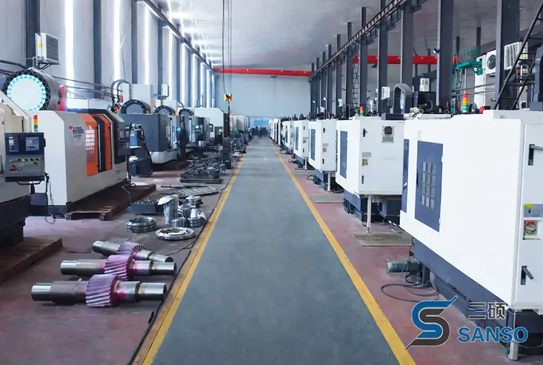
SANSO manufactures 90% of its squeeze roll assemblies in-house. This control
over precision, combined with imported hydraulic valve groups, ensures
consistent weld bead height under 0.5 mm even during speed ramps.
4. Cooling and Straightening: The Post-Process Handoff
Higher speeds mean less time for the weld to cool naturally. Inadequate
cooling affects the metallurgical structure. The weld zone may retain excessive
heat, leading to coarse grain structures and reduced ductility.
Lengthening the water cooling section and applying turbulent cooling
technology improves heat transfer. This prepares the weld for the straightening
rolls without residual stress. In-line eddy current testing provides immediate
feedback. If the system detects anomalies, it triggers an automatic alert,
allowing operators to adjust parameters before a full shift of scrap is
produced.
SANSO designs its cooling sections with enough capacity for speeds well above
typical running conditions. We also provide the calibration tools for eddy
current testers, helping you correlate machine settings with actual weld
integrity.
How SANSO Supports Your Speed Optimization Journey
Speed optimization is not a standalone project. It requires a partner who
understands the entire rolling process.
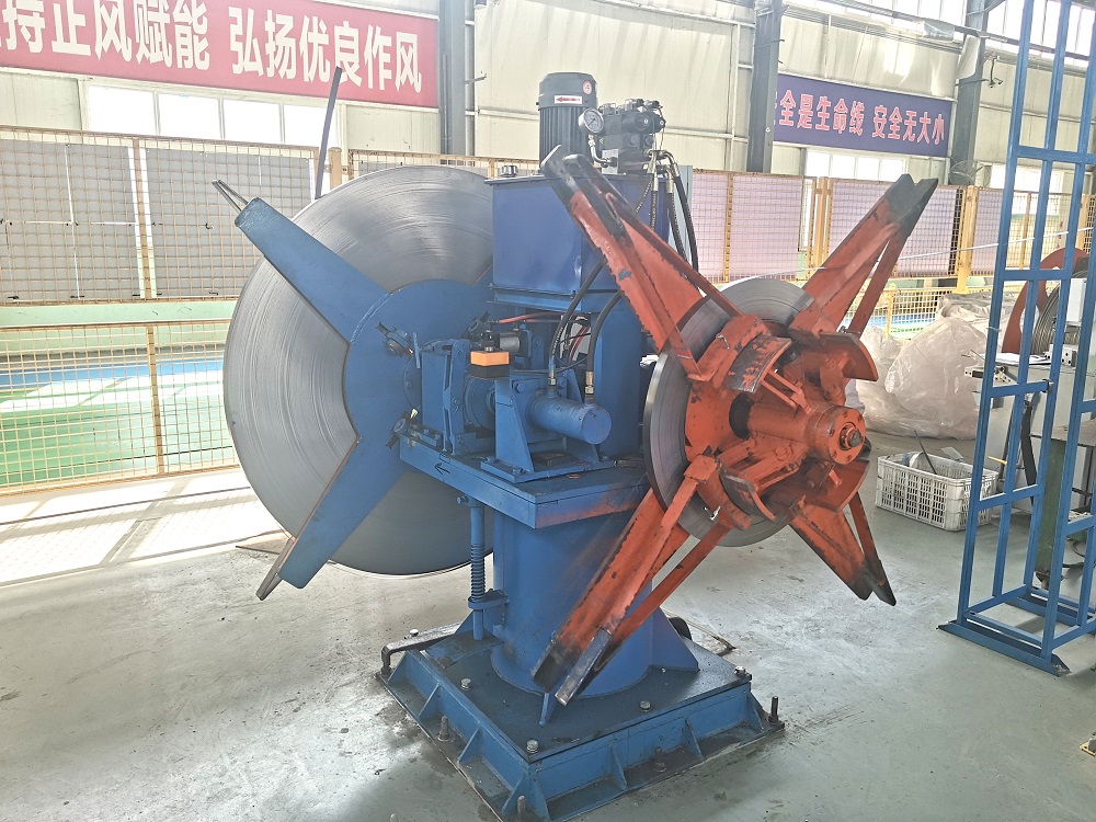
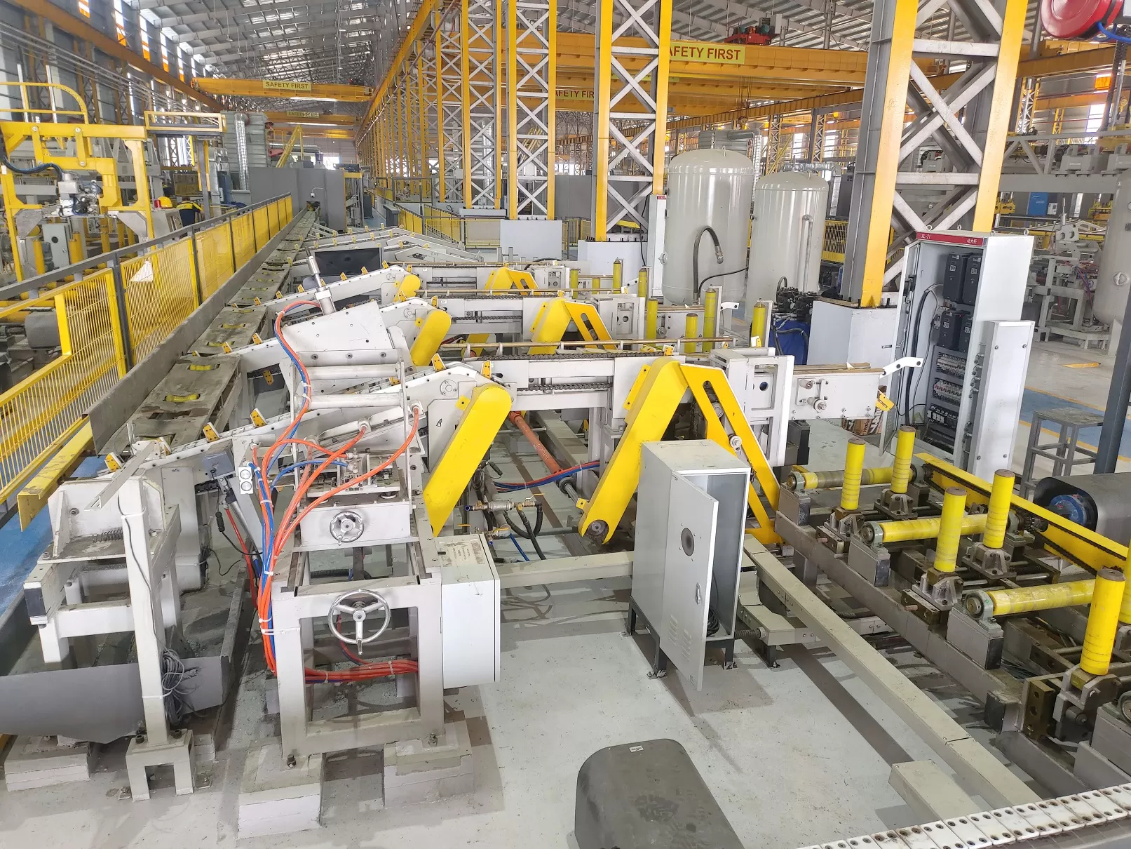
One-stop responsibility. SANSO manufactures the core
components of the complete line—from the uncoiler to the packing station. This
means when we optimize speed, we do not encounter bottlenecks where a fast
welder outruns the forming section or the cut-off saw. The entire line moves in
synchrony. We have already balanced the torque, tension, and acceleration
profiles across all stations.
Design and commissioning expertise. Our engineers do not sit
in an office drawing diagrams. They have field experience. They have started up
hundreds of mills under real production conditions. This practical knowledge
informs our design and our commissioning service. We offer "speed ramp-up
accompaniment" where our team works alongside yours to find the optimal speed
sweet spot for your specific material grades and thickness ranges.
Capacity across diameters. Whether you produce 8 mm
precision tubes or 508 mm large-diameter structural pipes, SANSO has a stand
stiffness classification that matches your application. Our modular design
approach allows us to scale rigidity and power without compromising stability at
higher speeds.
Real-World Results: Two Case Studies
The theory matters, but results speak louder. Here are two examples from our
customer base.
Case A: Small diameter tube (φ32 mm × 1.5 mm). The customer
ran at 80 m/min but suffered periodic pinholes in the weld. SANSO adjusted the
roll angles on stands 5 through 7 and recalibrated the HF tracking algorithm.
The speed increased to 110 m/min. The flattening test passed without failure.
Weld acceptance climbed from 97.3% to 99.6%.
Case B: Large diameter structural pipe (φ219 mm × 6.0 mm). The mill was limited to 18 m/min due to burn-through risks. SANSO upgraded the
HF generator to 600 kW and enhanced the squeeze roll cooling circuit. The line
now runs at 25 m/min. Unit energy consumption dropped by 9% because the higher
speed reduced the specific energy per ton.
These are not laboratory results. They are production numbers from plants
running three shifts. They demonstrate that speed and quality are not opposing
forces. They are two outcomes that can be aligned with the right engineering
approach.
Frequently Asked Questions
Q1: What is the most common cause of weld defects when increasing
roll forming tube mill speed?
A1: The most frequent cause is insufficient heat input per
unit length. As speed goes up, the material spends less time in the HF field. If
the power does not increase accordingly, the edges do not reach proper forging
temperature. This produces a cold weld that may look solid on the surface but
will fail under mechanical testing.
Q2: Can I optimize speed without upgrading my HF
generator?
A2: In many cases, yes—but only up to a point. If your
generator has adequate power reserves, you can adjust the tracking algorithm to
deliver more power at higher speeds. However, if the generator is near its
limit, you may need an upgrade. A proper assessment of your current power and
impedance matching is the first step.
Q3: How do I know if my vibration issues are caused by speed or by
roll wear?
A3: Roll wear typically causes consistent patterns—like a
periodic mark on the tube surface. Speed-related vibration often shows up as
random edge flutter or impingement point drift. You can test this by running a
short length at high speed with new rolls. If vibration still appears, the issue
is likely in the stand rigidity or the strip tension profile.
Q4: What is the ideal response time for a squeeze pressure control
system?
A4: The system should respond to a speed change command
within 50 milliseconds. Delays longer than this allow the squeeze gap to drift
during acceleration. SANSO's hydraulic servo systems meet this benchmark using
proportional valves and high-speed pressure transducers.
Q5: How often should I recalibrate the HF tracking
system?
A5: The calibration should be checked whenever you change
material grade, thickness, or line speed setpoint. We recommend a full
calibration check during every major setup change. Additionally, the system
should perform a self-check during each coil change to verify the pyrometer
readings and power output.
Final Thoughts
Pushing your roll forming tube mill to higher speeds is not a gamble. It is a
calculated technical exercise. The rewards are substantial—lower costs, higher
throughput, and better competitiveness. But the path requires attention to
mechanical rigidity, forming precision, and energy control.
SANSO has been on this path for over 20 years. We do not just build machines.
We partner with our customers to find the speed that works for their specific
production mix. Our team offers a free, no-obligation assessment of your current
speed and welding parameters. We will send you a customized report that outlines
your potential for improvement.
If you are ready to take your production to the next level, contact our
technical support team. Tell us your tube size, wall thickness, and current
speed. We will show you what is possible with a systematic approach to
optimization.
Contact SANSO Machinery today.
Email: info@sansohftubemill.com
Phone:
International Business: +86 13303118751
Domestic Business: +86 18603112509