In high-frequency induction welded (HFIW) pipe manufacturing, process continuity is a major determinant of product quality and operational yield. The modern carbon steel and stainless steel tube mill relies on a series of synchronized mechanical operations to transform flat steel strip into formed, welded, sized, and cut profiles. Among these operations, the transition between individual steel coils represents a vulnerable phase. If the forming and welding sections must stop every time a raw material coil is depleted, the localized heat input from the welding generator causes structural weakness, dimensional variance, and material waste at the joint. To prevent these interruptions, manufacturers integrate specialized storage systems to maintain a constant material flow.
As an engineering partner in the pipe production sector, SANSO focuses on the development of robust raw material handling and entry section machinery designed to stabilize line tension and feeding speed. A primary component in this sequence is the Strip Accumulator, which buffers sufficient steel strip to allow the entry shear and end welder to join the tail of the expiring coil to the leading edge of the incoming coil while the production mill continues to run at nominal speed.
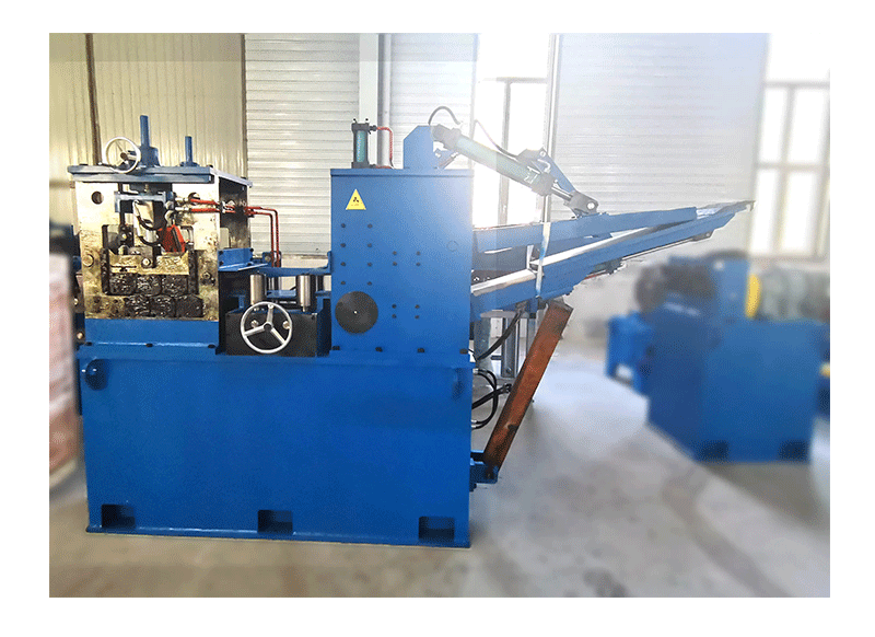
During a coil changeover, the entry section of the tube mill—comprising the uncoiler, flattener, and shear-and-weld unit—must come to a complete standstill. This stop is necessary for the operator to square the strip ends and perform a high-strength butt weld to connect the two coils. Without an intermediary storage reservoir, this standstill would force the entire forming mill to stop.
A mill shutdown presents several engineering difficulties:
Thermal Concentration: The high-frequency welder continues to emit localized thermal energy at the squeeze rolls when the strip stops, causing burn-through or altering the heat-affected zone (HAZ) metallurgy.
Dimensional Deviation: Stopping the mill alters the dynamic roll pressure in the forming passes, resulting in tube outer diameter (OD) and wall thickness deviations.
Tooling Wear: Frequent deceleration and acceleration cycles increase mechanical fatigue on roll shafts, bearings, and gearboxes.
By employing a continuous feeding method, the downstream forming, welding, sizing, and cutting processes proceed without speed fluctuations, maintaining consistent quality across the entire production run.
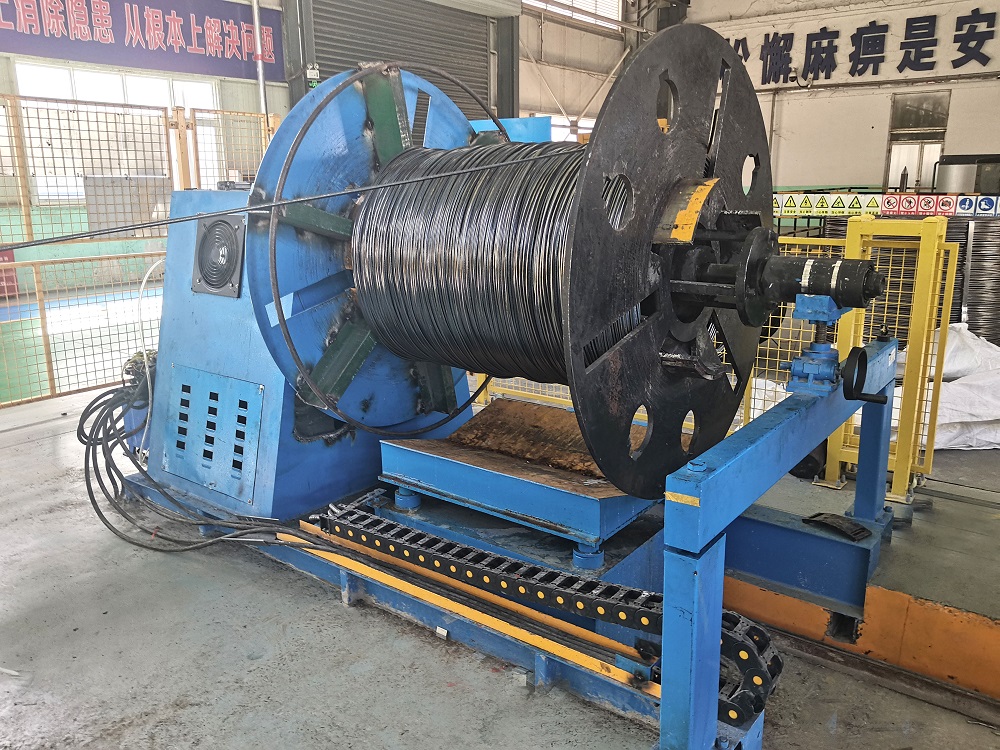
The core objective of a storage unit is to decouple the entry section speed from the forming section speed. This decoupling is achieved by accumulating a calculated length of steel strip within a controlled space. When the entry section is stopped for coil joining, the forming section pulls strip directly from the stored volume in the accumulator.
The accumulation cycle consists of three distinct phases:
Accumulation Phase (Filling): When the new coil is threaded and the entry section is restarted, the entry feed rolls run at a speed significantly higher than the forming mill speed (often 1.5 to 2.5 times faster). This speed differential fills the storage unit to capacity.
Steady-State Phase (Balanced Run): Once filled, the entry section speed is synchronized with the forming section speed. The strip passes through the storage unit without changing the stored volume.
Discharge Phase (Emptying): When the entry section stops for a coil change, the forming mill continues drawing material from the accumulator. The stored strip volume decreases progressively until the new weld is completed and the entry feed is re-engaged.
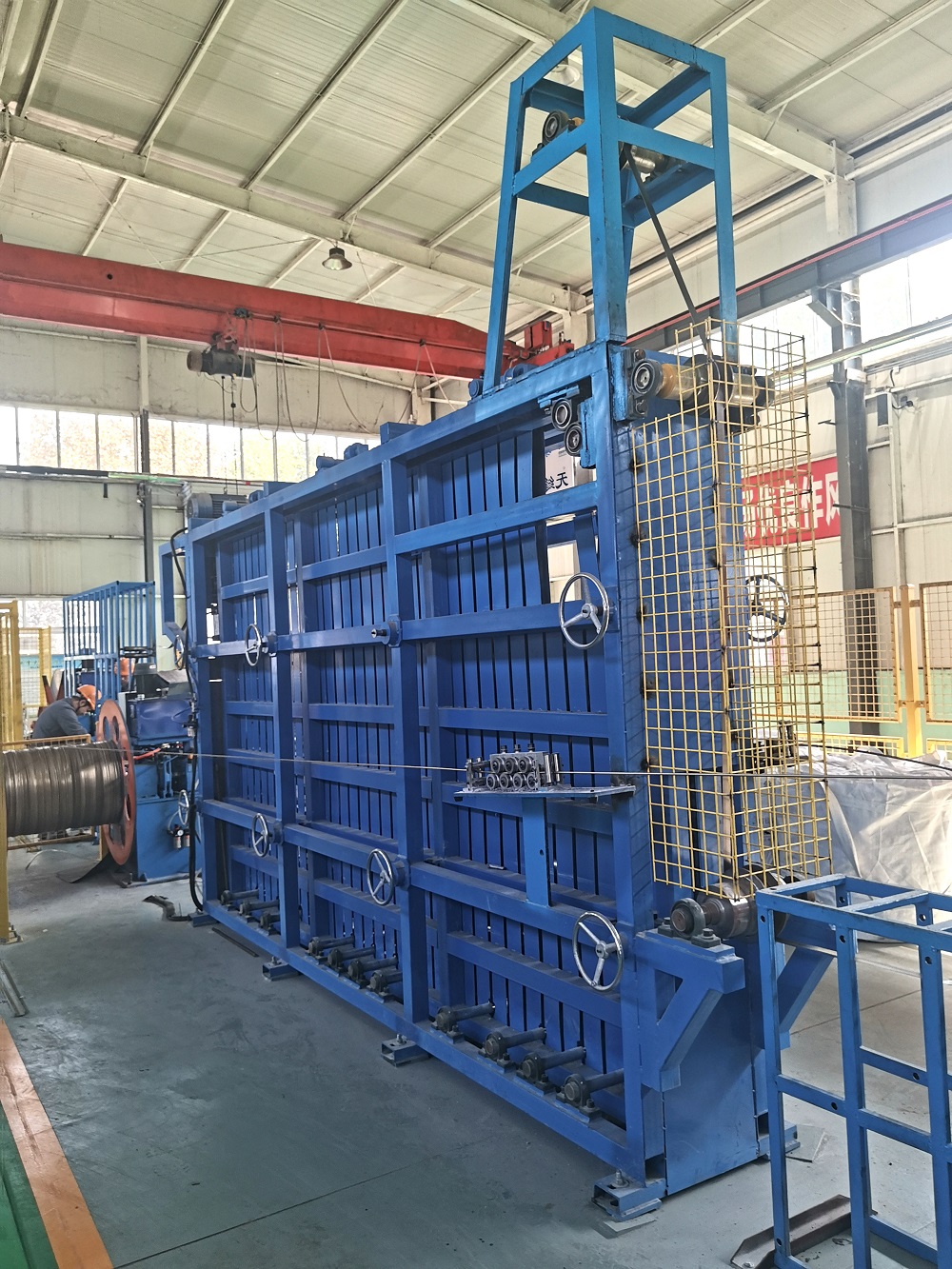
The horizontal spiral configuration stores the strip in a flat, concentric loop on a series of supporting rollers. The strip is fed into the outer diameter of the basket and is pulled out from the inner diameter (or vice versa, depending on the specific loop geometry). This design is highly space-efficient and is commonly utilized for light to medium wall thicknesses. Because the strip is guided along its natural flat bending plane, the mechanical strain on the edges is kept to a minimum.
For heavier wall thicknesses or high-yield strength steel grades, a vertical loop configuration is sometimes utilized. In this setup, the strip is guided over a high-elevation tower or down into a deep pit, forming a long vertical loop. The gravity-assisted loop control provides a simplified mechanical layout, though it requires substantial vertical space or civil excavation work. The choice between horizontal and vertical systems depends on factory floor layouts, strip width-to-thickness ratios, and material mechanical properties.
Modern tube mills operate under tight dimensional tolerances. Designing an entry line requires a precise understanding of the raw material characteristics, including strip width, thickness, yield strength, and the target mill speed. For instance, high-strength low-alloy (HSLA) steels have a high springback potential and require robust guiding systems to prevent the outer loops of a spiral storage unit from uncoiling prematurely.
The engineering team at SANSO analyzes these material properties to configure entry systems that prevent coil set memory issues. The roll tooling, basket diameter, and entry pinch roll design must be matched to the yield limits of the thickest and widest strip scheduled for production to ensure smooth feeding without permanent edge deformation.
For applications where surface finish is critical, such as decorative stainless steel tubing, automotive exhaust components, or coated structural profiles, preventing friction damage during accumulation is a key priority. Inside a horizontal Strip Accumulator, relative motion between adjacent strip loops or between the strip and the mechanical guides can cause surface scratching.
To address this, several preventive design measures are implemented:
Non-Metallic Contact Surfaces: Guide rollers and basket wear plates are lined with high-density polyurethane, nylon, or composite materials to prevent steel-on-steel friction.
Active Tension Regulation: Variable-speed drives on the entry pinch rolls maintain minimum back-tension, preventing loops from collapsing or rubbing excessively against each other.
Precision Loop Alignment: Centralizing guides adjust to the precise strip width, preventing lateral wandering that could scuff the strip edges.
Determining the physical size of a storage system requires careful calculation of the necessary buffering time. The basic formula to determine the required storage capacity is as follows:
L_a = V_m * T_w * k
Where:
L_a: Minimum accumulated strip length required (meters)
V_m: Maximum operating speed of the forming mill (meters/minute)
T_w: Total time required to complete the shear and weld cycle (minutes)
k: Safety factor (typically between 1.15 and 1.25, accounting for operator delays or system acceleration lag)
For example, if a tube mill runs at a maximum speed of 80 m/min, and the shear-and-weld operation takes 1.5 minutes to complete, with a safety factor of 1.2, the required active storage length is:
L_a = 80 * 1.5 * 1.2 = 144 meters
The mechanical footprint of the accumulator must be large enough to contain this length without exceeding the minimum bending radius of the thickest strip material.
Achieving stable high-speed performance requires a closed-loop control system. The accumulation process is monitored by photoelectric sensors, ultrasonic level detectors, or rotary encoders mounted on the guiding arms. These sensors continuously track the fill state of the accumulator.
The automation system performs the following feedback loops:
Speed Synchronization: When the accumulator is depleted, the control system ramps up the entry section drive motors to their maximum filling speed.
Overspeed Protection: As the accumulator nears capacity, the drive speed is gradually reduced to match the mill speed, avoiding mechanical shock when the filling phase ends.
Emergency Stop Integration: If the shear-and-weld operation takes longer than the buffered time, the system sends a deceleration signal to the forming mill to stop it safely before the accumulator is completely emptied, protecting the strip from tearing.
Through integrated control platforms, SANSO coordinates the interaction between the uncoiler, flattener, joiner, and the storage system, reducing manual operator intervention and lowering the risk of feed-related line stops.
Every tube production facility operates under unique physical and operational constraints. Selecting the correct configuration requires a balance between material thickness, width, yield strength, and available shop floor space. We invite engineering managers and production directors to discuss their specific line requirements with our design team. Our engineers provide custom layout drawings, material flow analyses, and equipment specifications tailored to your production targets. Please contact us to submit your project parameters and receive a detailed engineering proposal.
Q1: Why is a Strip Accumulator necessary for a high-frequency welded tube mill?
A1: High-frequency induction welding requires consistent heat input and constant strip speed to form a metallurgical weld of uniform quality. If the mill stops to join raw material coils, the local temperature profile at the weld point changes, causing defective seams, scrap material, and potential damage to the squeeze rolls. The accumulator provides a continuous buffer of strip, enabling the mill to maintain steady-state operations while the entry section is stopped for coil welding.
Q2: What is the primary difference between a horizontal spiral accumulator and a basket-type accumulator?
A2: A horizontal spiral accumulator organizes the strip in flat, concentric loops on a horizontal plane, guiding the material smoothly with minimal edge strain, which makes it suitable for high-speed mills and surface-sensitive materials. A basket-type accumulator (or loose loop accumulator) allows the strip to accumulate in a less structured, free-floating loop configuration within a retaining cage, which is mechanically simpler but can lead to surface scratching and is generally used for structural, less surface-critical profiles.
Q3: How does the thickness of the steel strip affect the design of the Strip Accumulator?
A3: Strip thickness directly dictates the minimum permissible bending radius of the steel. Thicker strips require larger guide rolls and a larger internal basket diameter to prevent the material from undergoing permanent plastic deformation or "coil set." Additionally, thicker materials demand higher drive motor torque in the entry pinch rolls to manage the resistance of the heavy-gauge steel strip during high-speed filling.
Q4: How can surface scratching be prevented when running polished stainless steel or pre-galvanized strips?
A4: Scratching is mitigated by avoiding metal-on-metal contact. This is achieved by cladding the guiding rolls, lateral guides, and storage basket pathways with non-marring materials such as polyurethane, ultra-high-molecular-weight (UHMW) polyethylene, or heavy-duty nylon. Additionally, maintaining precise dynamic tension control prevents the nested loops from collapsing and sliding against one another during accumulation and discharge.
Q5: What happens if the operator cannot complete the end-welding process before the accumulator is empty?
A5: Modern automated entry systems are equipped with safety sensors that monitor the remaining strip length in the storage unit. If the operator cannot complete the weld within the buffered time, the control system initiates a controlled deceleration of the forming mill. This stops the mill safely before the tail end of the strip exits the accumulator, preventing strip breakage, guiding damage, and threading difficulties.